
Push switch

Active Publication Date: 2011-11-24
ALPS ALPINE CO LTD
View PDF3 Cites 6 Cited by
  • Summary
  • Abstract
  • Description
  • Claims
  • Application Information

AI Technical Summary

Benefits of technology

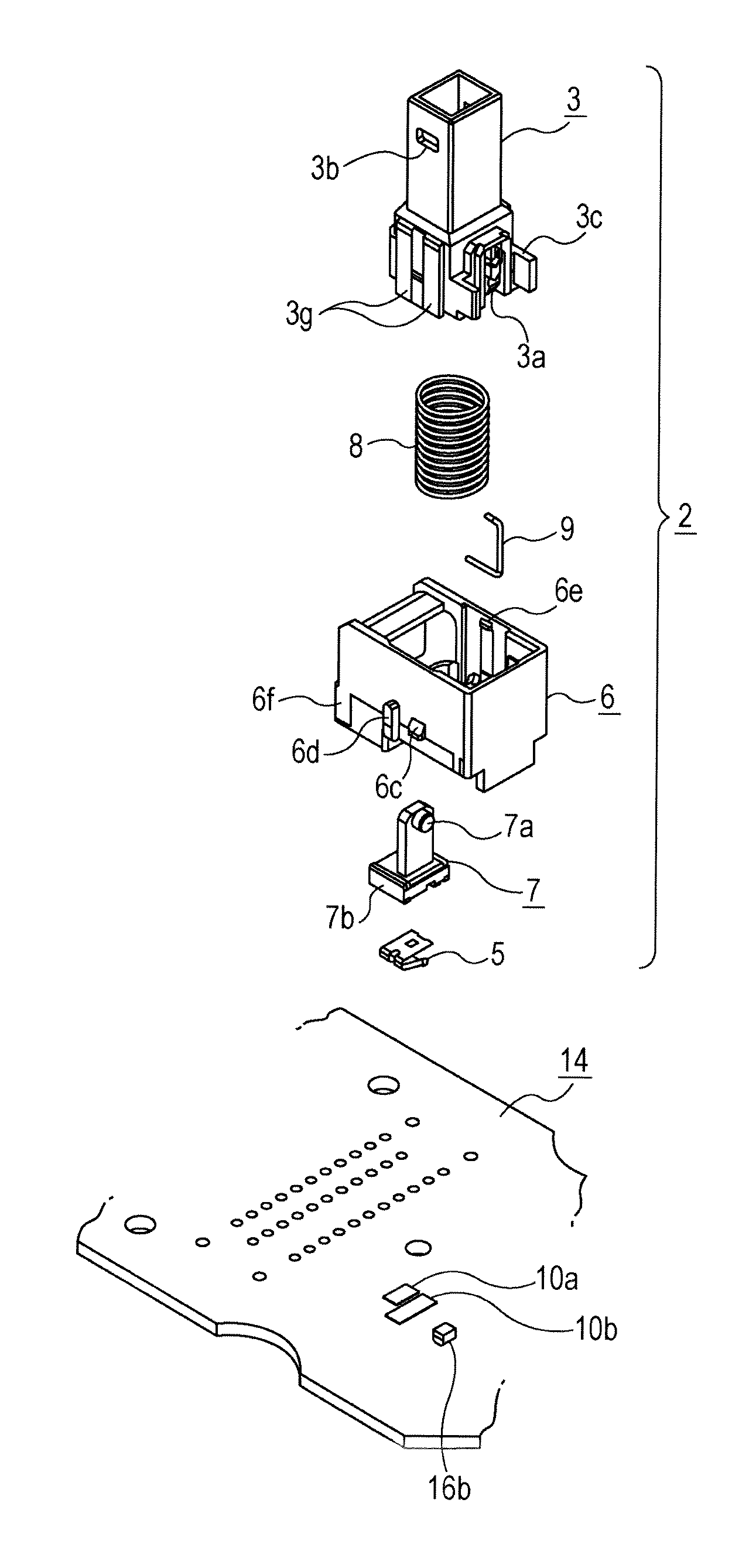
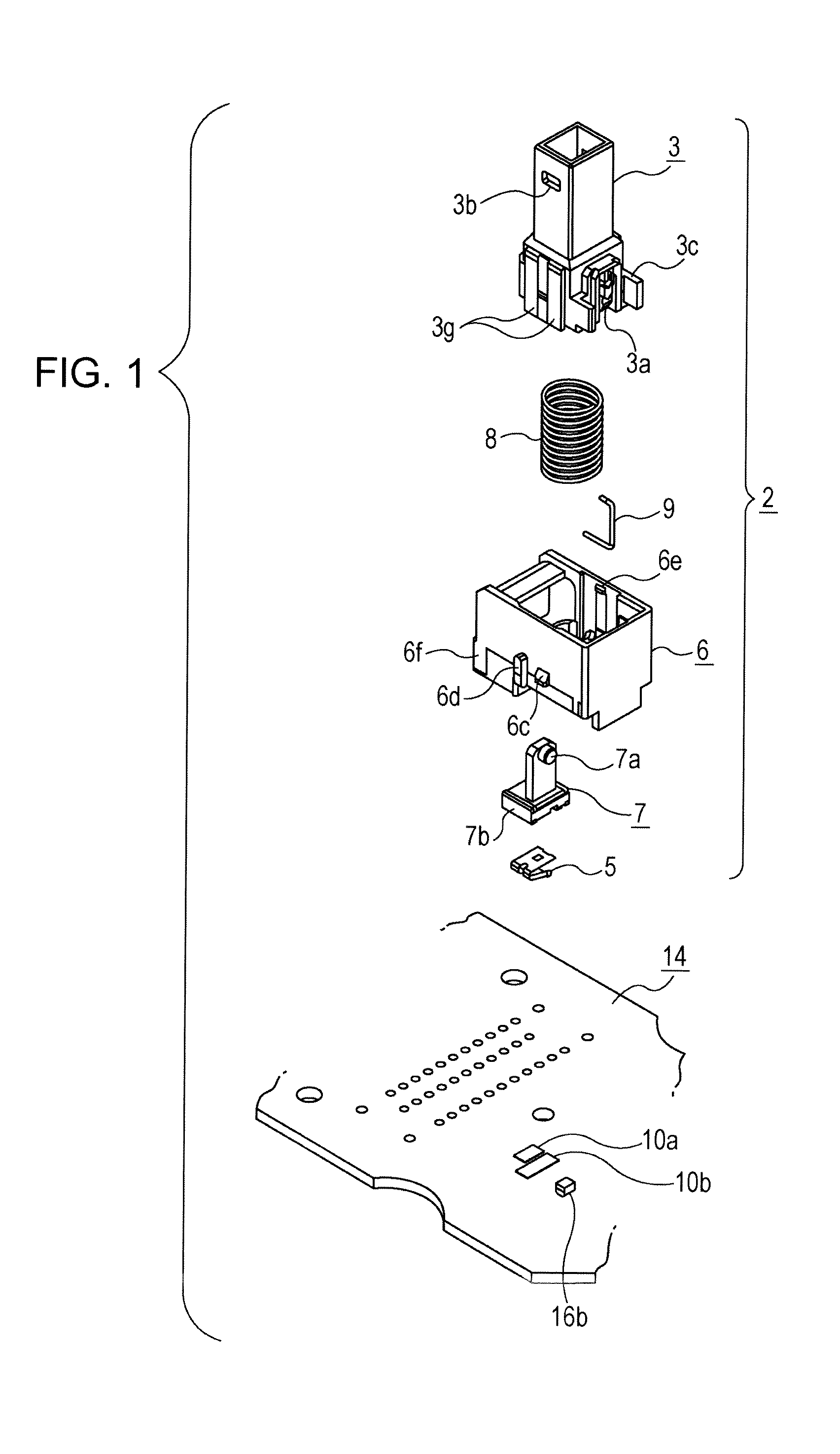
[0012]In the push switch with the above-described configuration, the housing is attached to the outer casing and a space is provided between the housing and the circuit board. Accordingly, an operating load applied to the operating slider acts on the outer casing through the housing and the operating load hardly acts on the circuit board. If an excessive operating load is applied, therefore, there is no fear of occurrence of damage, e.g., a crack in a soldered joint caused by deflection of the circuit board. Further, since the space is provided between the housing and the circuit board, a circuit pattern and electronic components can be arranged in an area in the space, thus increasing an effective area in the circuit board. Moreover, if the position of the fixed contact on the circuit board is shifted, the timing when the sliding member is brought into contact with or separated from the fixed contact can be changed. Accordingly, the timing of switching to the ON state can be easily adjusted depending on the intended use of the push switch. In addition, the actuator is slid in the direction substantially orthogonal to the push operation direction to switch the push switch between the ON and OFF states. Accordingly, if an actuation stroke for the operating slider is set to long, the height of the housing can be prevented from increasing. Further, the heart cam mechanism provided for the push switch allows the engagement pin journaled by either one of the operating slider and the housing to be slid along the cam groove provided for the other one. Advantageously, the heart cam mechanism functions as a lock mechanism with a simple configuration and good space factor.
[0013]With the above-described configuration, the housing may be fixed, e.g., screwed to the outer casing. The outer casing can include an attachment frame such that the attachment frame extends vertically upwardly and downwardly therefrom, the attachment frame has a fastening hole, the housing includes an engagement hook protruding fr

Problems solved by technology

Accordingly, when the operating slider of the push switch is pushed by a large operating physical force, the circuit board is deflected, so that a soldered joint may be cracked.
In particular, when this kind of push switch is provided with a lock mechanism, a relativ

Method used


Image

  • Push switch
  • Push switch
  • Push switch

Examples


Example

[0027]The following description is intended to convey a thorough understanding of the embodiments described by providing a number of specific embodiments and details involving a push switch. It should be appreciated, however, that the present invention is not limited to these specific embodiments and details, which are exemplary only. It is further understood that one possessing ordinary skill in the art, in light of known systems and methods, would appreciate the use of the invention for its intended purposes and benefits in any number of alternative embodiments, depending on specific design and other needs.

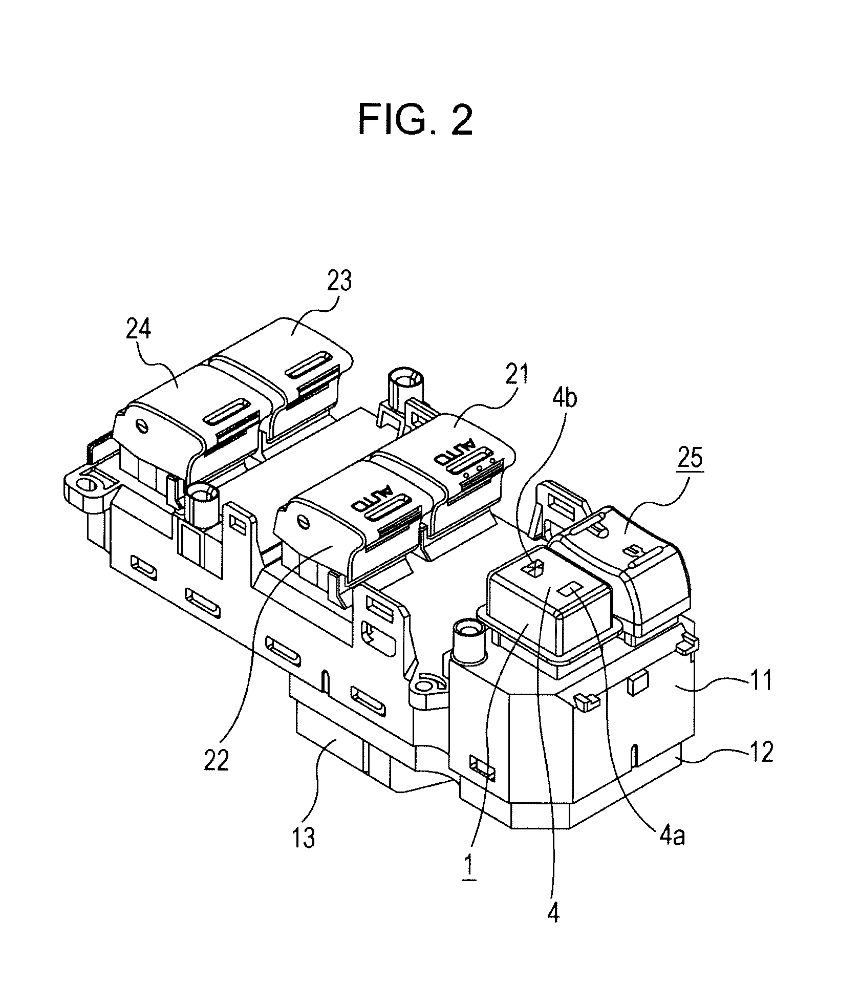
[0028]Various embodiments of the disclosure will be described below with reference to FIGS. 1 to 12. A switch unit illustrated in FIGS. 2 to 4 may be attached to the inside of a door of an automobile. This switch unit may include a plurality of switch devices including a push switch 1 according to this embodiment. Specifically, the switch unit may include four switch devices 21 ...


PUM


Abstract

A push switch includes an operating slider, an actuator with a sliding member, a return spring, a housing, a main body in which the operating slider, the actuator, and the return spring are supported by the housing, a heart cam mechanism (including an engagement pin and a cam groove) incorporated in the main body, an operating knob which caps the operating slider, and a fixed contact provided for a circuit board such that the sliding member is allowed to be brought into contact with and separated from the fixed contact. When the operating slider is moved upward or downward, the actuator is driven to be laterally slid. The housing is snap-fitted to an outer casing (upper casing) holding the circuit board. A space is provided between the housing and the circuit board.

Description

CROSS-REFERENCE TO RELATED APPLICATIONS[0001]This application contains subject matter related to and claims benefit of Japanese Patent Application No. 2010-118554 filed on May 24, 2010, which is hereby incorporated by reference.BACKGROUND OF THE DISCLOSURE[0002]1. Field of the Disclosure[0003]The present disclosure relates to a push switch with a locking mechanism, and in particular, relates to a push switch in which an actuator is slid in a direction substantially orthogonal to the direction in which the switch is pushed to switch between ON and OFF states.[0004]2. Description of the Related Art[0005]A push switch with a locking mechanism is designed such that when an operating member is pushed to turn on the switch (ON state), the operating member is locked in this state, and when the operating member is again pushed, the locked state is unlocked and the switch is returned to its OFF state. If a long actuation stroke is set, the push switch is often pushed with a relatively large ...

Claims


Application Information

Patent Timeline
IPC IPC(8): H01H13/14
CPCH01H13/023H01H2300/01H01H13/60H01H13/562
Inventor MIWA, TOSHITAKASUZUKI, HIROKI
Owner ALPS ALPINE CO LTD
Learn More