
Power System Frequency Inertia for Wind Turbines

a technology of power system and wind turbine, which is applied in the direction of electric generator control, machine/engine, greenhouse gas reduction, etc., can solve the problem that the classical synchronous generator is not well suited for wind turbine us

Inactive Publication Date: 2011-11-24
SIEMENS AG
View PDF2 Cites 38 Cited by
  • Summary
  • Abstract
  • Description
  • Claims
  • Application Information

AI Technical Summary

Benefits of technology

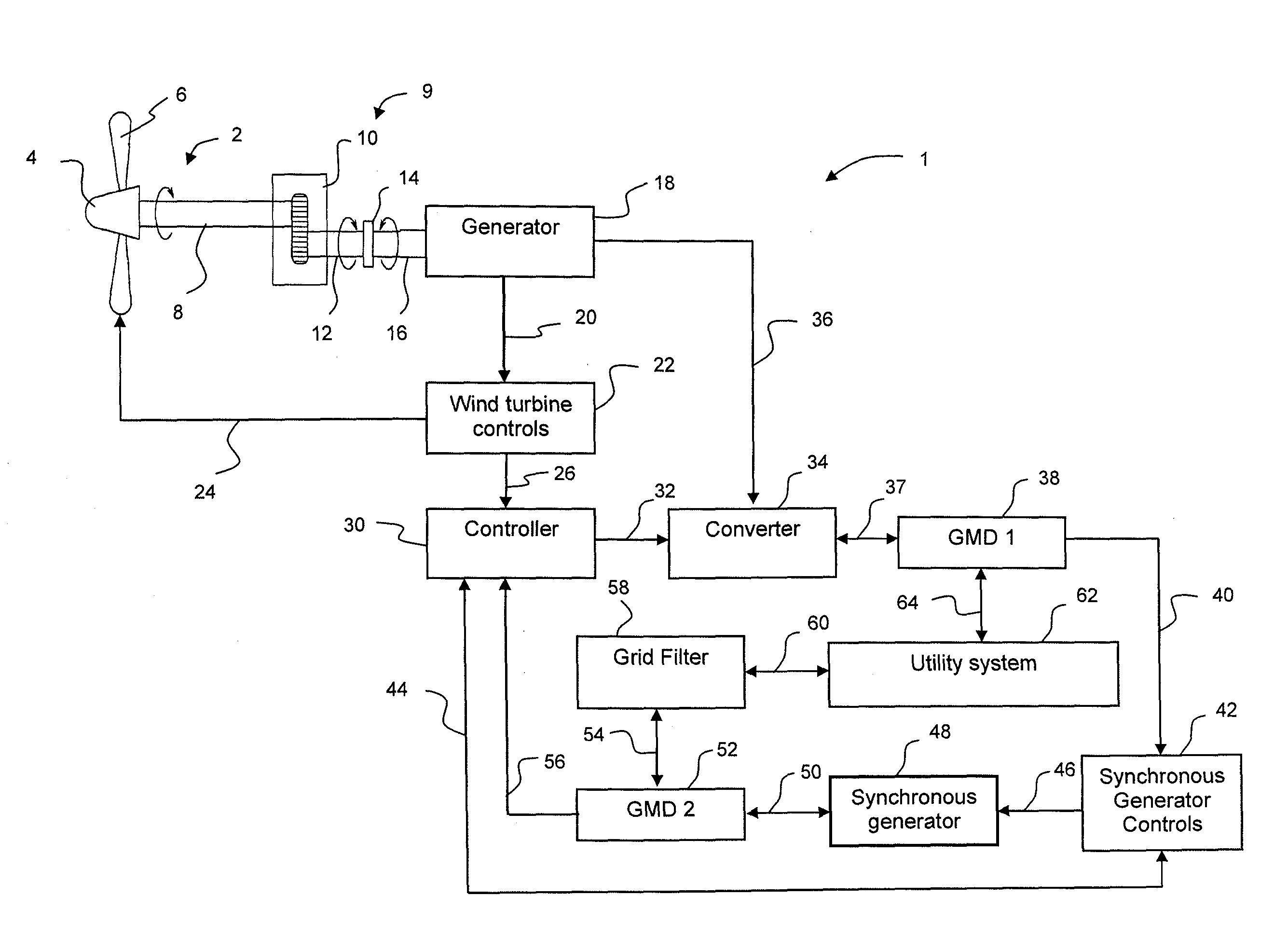
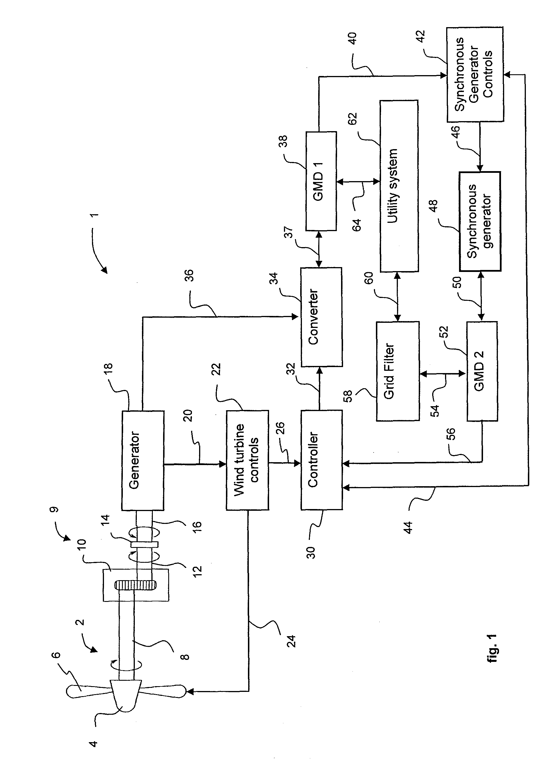
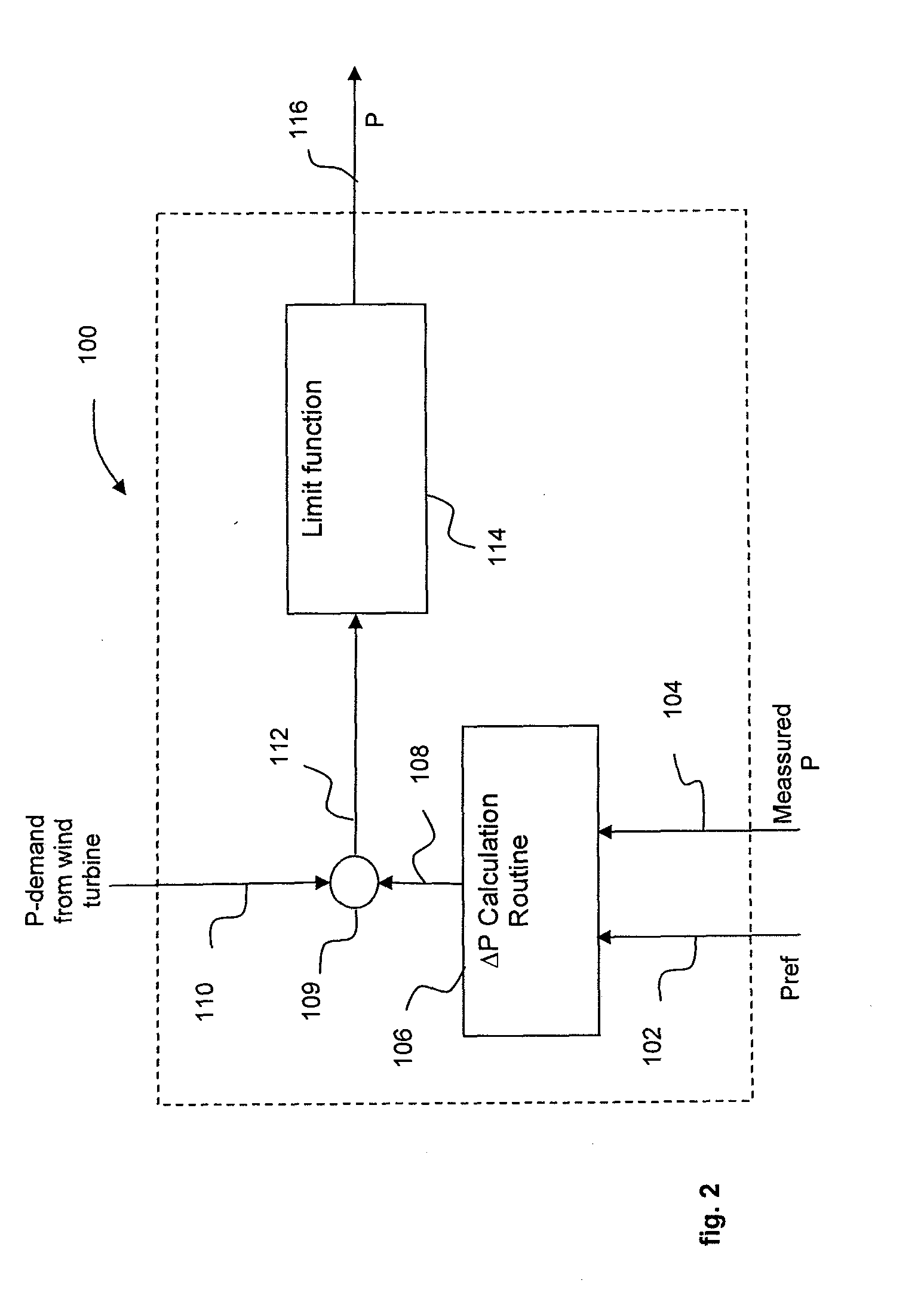
[0011]A grid measurement device is located between the synchronous generator and the grid in order to measure the current and power exchanged between the synchronous generator and the grid. The output of the grid measurement device is by means of communication transmitted to a controller that is arranged for adjusting the output power of the wind turbine as a function of the power and current that is measured by the grid measurement device. The controller is in one embodiment of the invention an integrated part of an internal wind turbine controller. In another embodiment the controller is an external controller using means of communication between the controller and the wind turbine. The wind turbine is configured to provide current and power to the utility system as a function of the output of the grid measurement device and this way contributing to the stabilization of the grid frequency in case of imbalance.
[0036]In another embodiment of the invention the synchronous generator is connected to a controller in order to use the synchronous generator for generation or absorption of reactive power, and hereby providing the possibility for improved grid support.

Problems solved by technology

However, classical synchronous generators are not well suited for use on wind turbines, since their very stiff characteristics are not compatible with wind turbine application.
Secondly, feed-back response elements may occur where the wind turbine generator system regulates in response to self-created artifacts.
Furthermore, in the normal configuration wind turbines do not contribute to the frequency stabilization of the utility system.

Method used


Image

  • Power System Frequency Inertia for Wind Turbines
  • Power System Frequency Inertia for Wind Turbines
  • Power System Frequency Inertia for Wind Turbines

Examples


Embodiment Construction

[0010]An exemplary embodiment of the invention includes a wind turbine system comprising of at least one wind turbine generator operable to supply wind turbine power to a utility system, and at least one synchronous generator that is operated in parallel to the wind turbine generator. The wind turbine generator is interfaced to the utility system using a power converter.

[0011]A grid measurement device is located between the synchronous generator and the grid in order to measure the current and power exchanged between the synchronous generator and the grid. The output of the grid measurement device is by means of communication transmitted to a controller that is arranged for adjusting the output power of the wind turbine as a function of the power and current that is measured by the grid measurement device. The controller is in one embodiment of the invention an integrated part of an internal wind turbine controller. In another embodiment the controller is an external controller usin...


PUM


Abstract

A wind turbine system and method are provided. The wind turbine system includes a wind turbine operable to supply wind power to an utility system; a synchronous generator coupled to the utility system; a grid measurement device arranged for measuring the current and power that is exchanged between the synchronous generator and the utility system; a controller for adjusting the output power of the wind turbine as a function of the power and current that is measured by the grid measurement device; and a means of communication between the grid measurement device, controller and / or the wind turbine, wherein the wind turbine is configured to provide current and power to the utility system as a function of the measured power and current of the grid measurement device.

Description

BACKGROUND OF THE INVENTION[0001]The invention relates generally to the field of wind turbine generators used for power generation for utility grids, and more particularly to techniques for ensuring grid compliance of wind turbine generators, including stabilizing power during transient conditions.[0002]A wind turbine generator generally includes a wind rotor that converts wind energy into rotational motion of a turbine shaft, which in turn drives the rotor of an electrical generator to produce electrical power.[0003]Modern wind turbine generator installations typically take the form of a wind farm having multiple wind turbine generators connected to a common wind farm power grid. This wind farm grid is connected to a utility grid, either directly or through a substation which may include a step-up transformer.[0004]Individual wind turbines and wind farms are required to comply with the power quality requirements of the utility system operator. Such power quality requirements, often...

Claims


Application Information

Patent Timeline
Patent Type & Authority Applications(United States)
IPC IPC(8): H02P9/04
CPCF03D7/0224H02P2101/15F03D7/0284F05B2220/70642F05B2270/1032F05B2270/1033F05B2270/337H02J3/18H02J3/386H02P9/105H02P9/42Y02E10/723Y02E10/725Y02E10/763Y02E40/30F03D7/0272Y02E60/16Y02E70/30H02J3/30H02J2300/28H02J3/381Y02E10/72Y02E10/76H02J3/46
Inventor THISTED, JAN
Owner SIEMENS AG
Learn More