Power meter phase identification

a power meter and phase identification technology, applied in the direction of digital variable/waveform display, phase sequence/synchronization indication, instruments, etc., can solve the problem of inability to optimize the utilization of existing infrastructure, inability to connect too many users to one phase of voltage while too few are connected, and inability to accurately determine the phas

Inactive Publication Date: 2011-11-24
GENERAL ELECTRIC CO
View PDF7 Cites 39 Cited by
  • Summary
  • Abstract
  • Description
  • Claims
  • Application Information

AI Technical Summary

Problems solved by technology

However, over time, users may be added and removed from the network, which may result in an imbalance in the phase currents and voltage flow.
That is, too many users may be connected to one phase of voltage while too few are connected to a second and / or third phase.
This may result in a non-optimal utilization of the existing infrastructure.
However, there exist challenges in moving customers from one phase of voltage to another.
For instance, as customers are added to and subtracted from a power distribution network, the phase of voltage that a given customer is connected to may be difficult to ascertain without costly physical tracking (typically by a worker in the field) of a given power line to the network.
That is, while a load imbalance may be detected remotely, the phase to which the individual users are connected to may not be readily apparent without physically tracking the power lines from a substation to the respective user locations.

Method used


Image

  • Power meter phase identification
  • Power meter phase identification
  • Power meter phase identification

Examples


Embodiment Construction

[0013]Certain embodiments commensurate in scope with the originally claimed invention are summarized below. These embodiments are not intended to limit the scope of the claimed invention, but rather these embodiments are intended only to provide a brief summary of possible forms of the invention. Indeed, the invention may encompass a variety of forms that may be similar to or different from the embodiments set forth below.

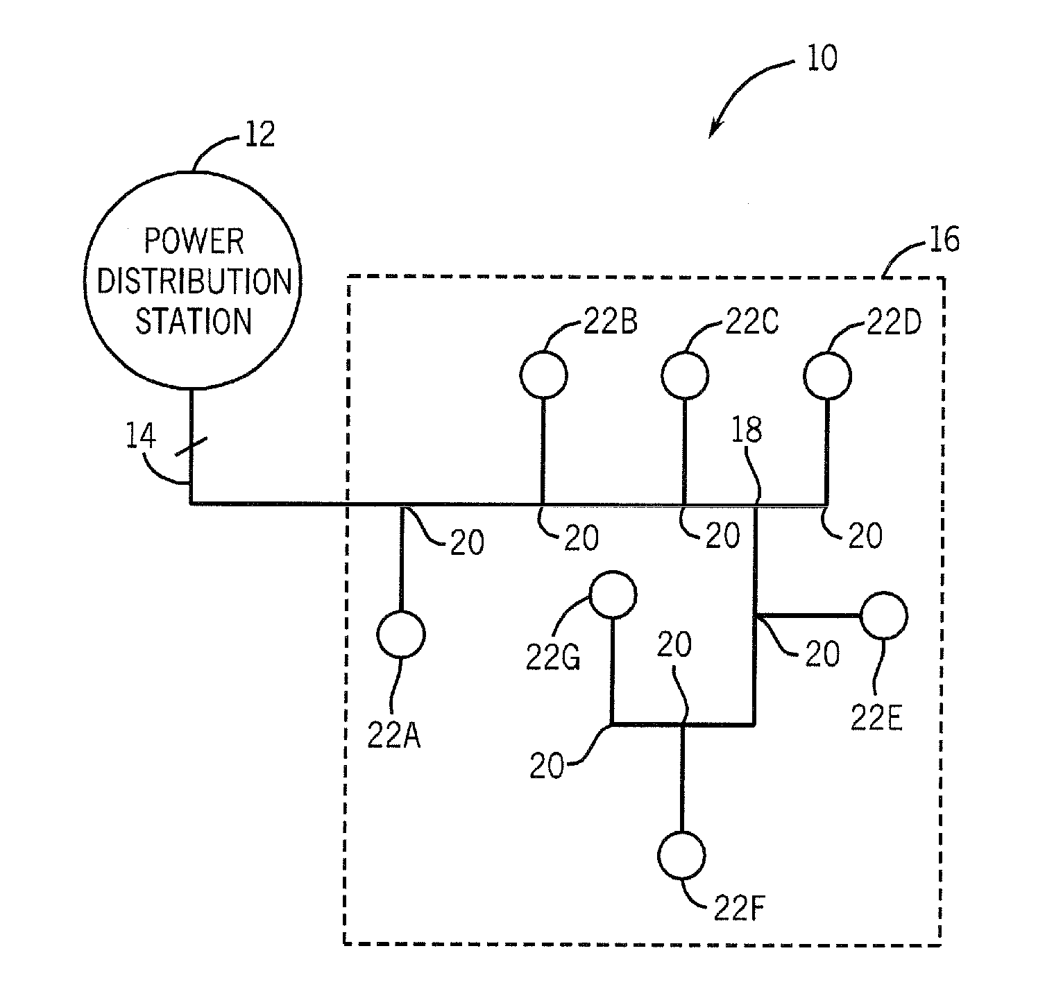
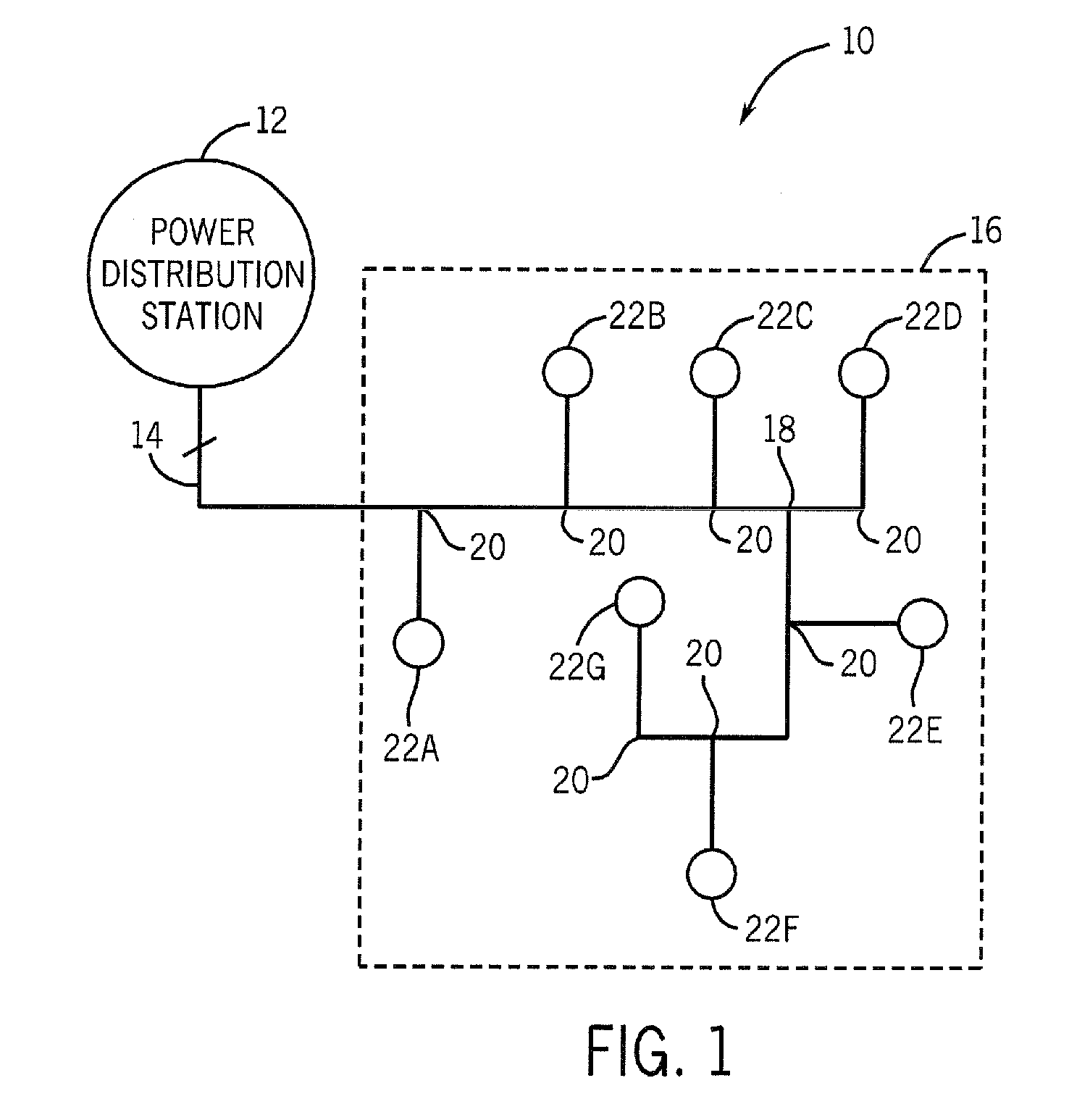
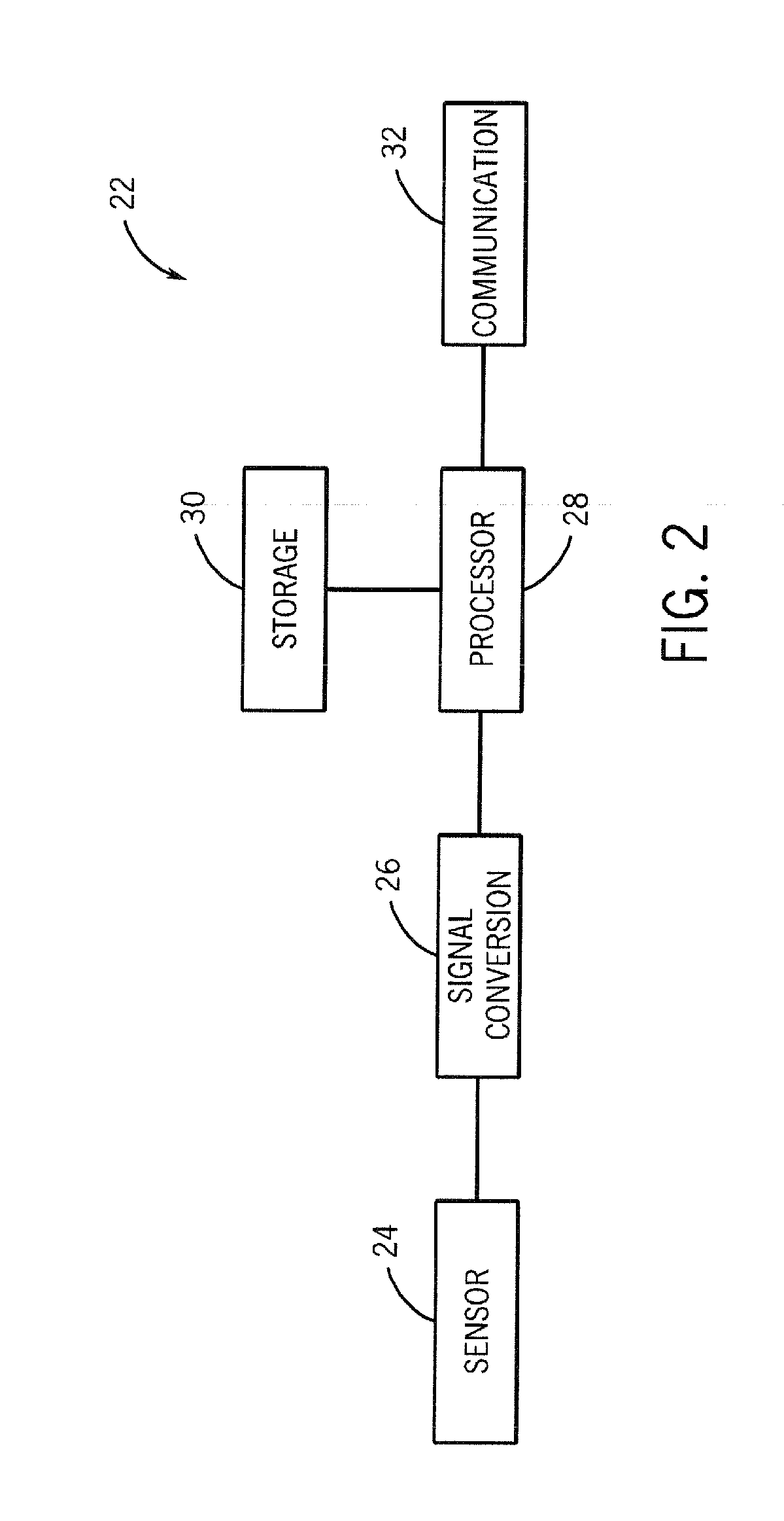
[0014]A method and system is described for identifying which phase of voltage a customer is connected to in a power grid. One or more power lines in the power grid may be used to transmit an injected signal along with the voltage transmitted along the lines. The injected signal may, for example, be injected at a power distribution substation of the power grid. This injected signal may travel over the one or more power lines of the power grid and may be detected at a phase detection device, for example, located at a user's residence or workplace or at, for example, ...


PUM


Abstract

Methods and systems are described for determining a phase of transmitted voltage. In one embodiment, a power distribution system may operate to transmit voltage and an injected signal. The system may also include a power meter that may receive the voltage and injected signal. The power meter may determine a phase of the received voltage based on the received voltage and the injection signal.

Description

BACKGROUND OF THE INVENTION[0001]This invention relates to the measurement and determination of the phase of electricity provided over a power distribution grid.[0002]Modern power distribution systems may deliver three phase voltage to users. That is, a power line may, for example, include a plurality of conductors each designated as a specific phase of voltage. Moreover, the power distribution system may be set up to operate such that the loads of the power line are balanced (e.g., the amount of power drawn from each phase output of, for example, a three-phase transformer, are equal). However, over time, users may be added and removed from the network, which may result in an imbalance in the phase currents and voltage flow. That is, too many users may be connected to one phase of voltage while too few are connected to a second and / or third phase. This may result in a non-optimal utilization of the existing infrastructure. One manner of overcoming this load imbalance may be to insti...

Claims


Application Information

Patent Timeline
Patent Type & Authority Applications(United States)
IPC IPC(8): G01R13/02
CPCG01R29/18
Inventor KOLWALKAR, AMOL RAJARAMTOMLINSON, HAROLD WOODRUFFSEN, BHASKARHERSHEY, JOHN ERIKKOSTE, GLEN PETER
Owner GENERAL ELECTRIC CO
Why Eureka
Try Eureka