

Fast acting distributed power system for transmission and distribution system load using energy storage units
a distributed power system and energy storage technology, applied in emergency power supply arrangements, process and machine control, instruments, etc., can solve the problem that systems rarely function for the purpose of supplying electric power, and achieve accurate and dynamic load and reserve times, reduce reliance on higher cost, and reduce cost
- Summary
- Abstract
- Description
- Claims
- Application Information
AI Technical Summary
Benefits of technology
Problems solved by technology
Method used
Image

Examples
Embodiment Construction
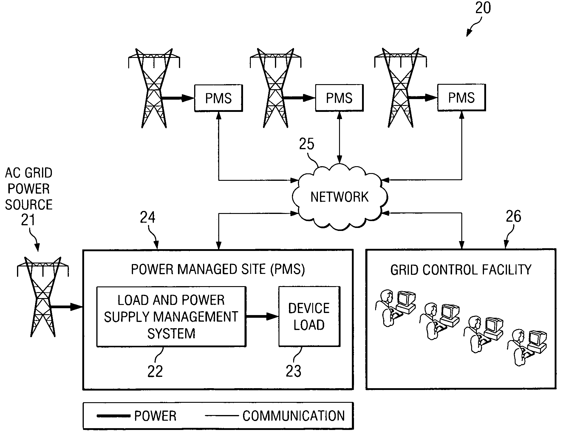
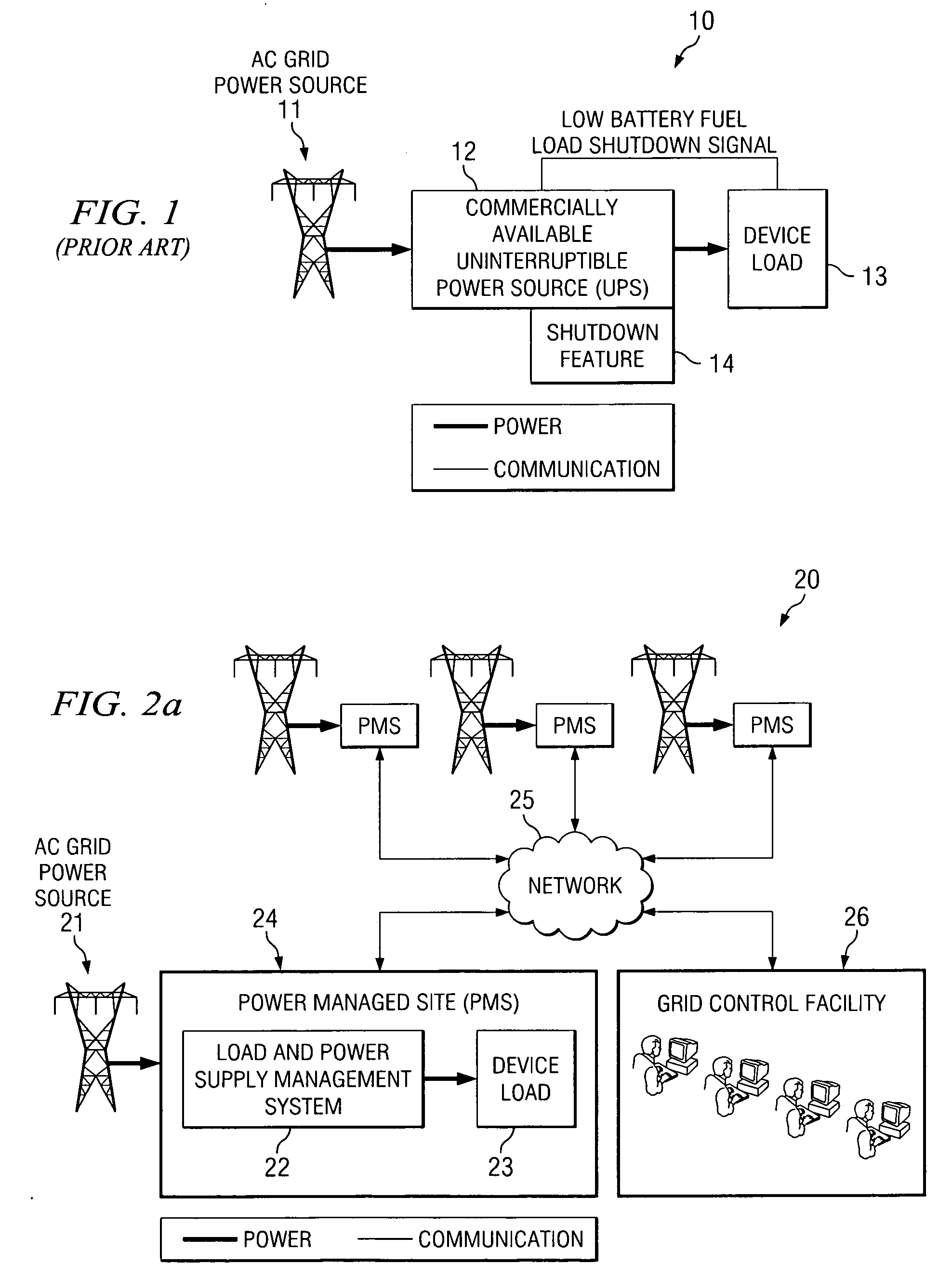
[0035]FIG. 2A depicts an arrangement of an embodiment of the invention. In FIG. 2A, a plurality of Power Managed Sites (PMS) 24 are connected to AC grid power sources 21. Note that each source 21 may comprise a different grid, a different portion of a grid, the same portion of the grid, or combinations thereof. Each PMS 24 is also connected to a grid control facility 26 through network 25, which may be a wide area network. Each PMS 24 may represent a home, school, business, other power consumer, or a component at one of those locations. Note that one location may have more than one component. Each PMS 24 includes a load management and power supply management system 22 and a device load 23. Management system tracks the demands of the load 23 and the amount of UPS power available at PMS 24, and sends this information to the grid control facility 26 on a period basis or continuous basis. The UPS Management System 20 is used to reduce AC Power requirements from the utility to the loads ...
PUM
 Abstract
Description
Claims
Application Information