Button activated spring-loaded hinge assembly

a technology of spring-loaded hinges and hinges, which is applied in the direction of wing accessories, electric apparatus casings/cabinets/drawers, wing accessories, etc., can solve the problems of high cost, relative complexity of manufacture, and high cost of threaded structures

Inactive Publication Date: 2011-11-24
SHENZHEN FUTAIHONG PRECISION IND CO LTD +1
View PDF1 Cites 12 Cited by
  • Summary
  • Abstract
  • Description
  • Claims
  • Application Information

AI Technical Summary

Problems solved by technology

This kind of hinge assembly includes threaded engagement of its parts and is relatively complicate to man

Method used


Image

  • Button activated spring-loaded hinge assembly
  • Button activated spring-loaded hinge assembly
  • Button activated spring-loaded hinge assembly

Examples


Embodiment Construction

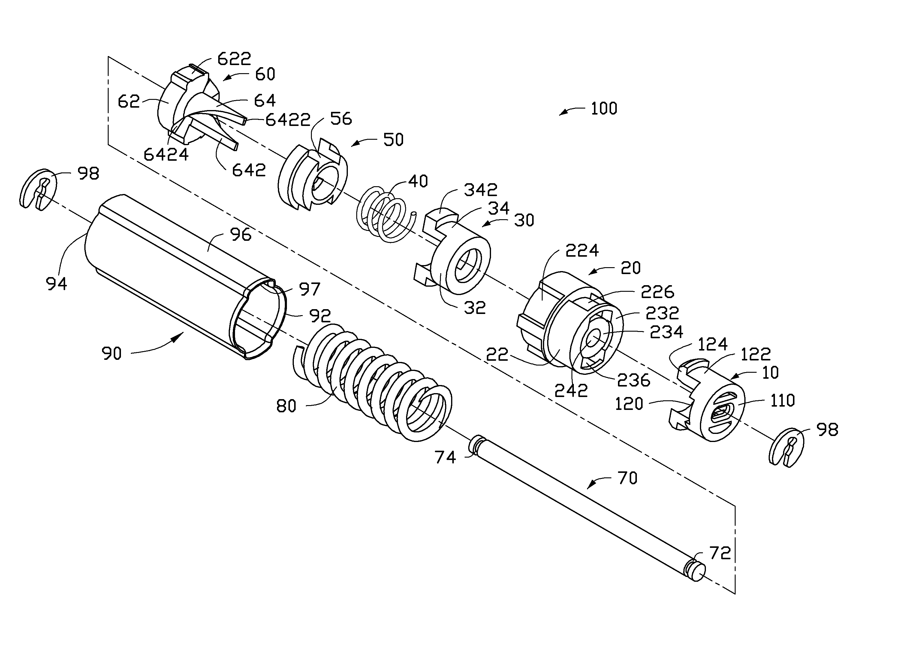
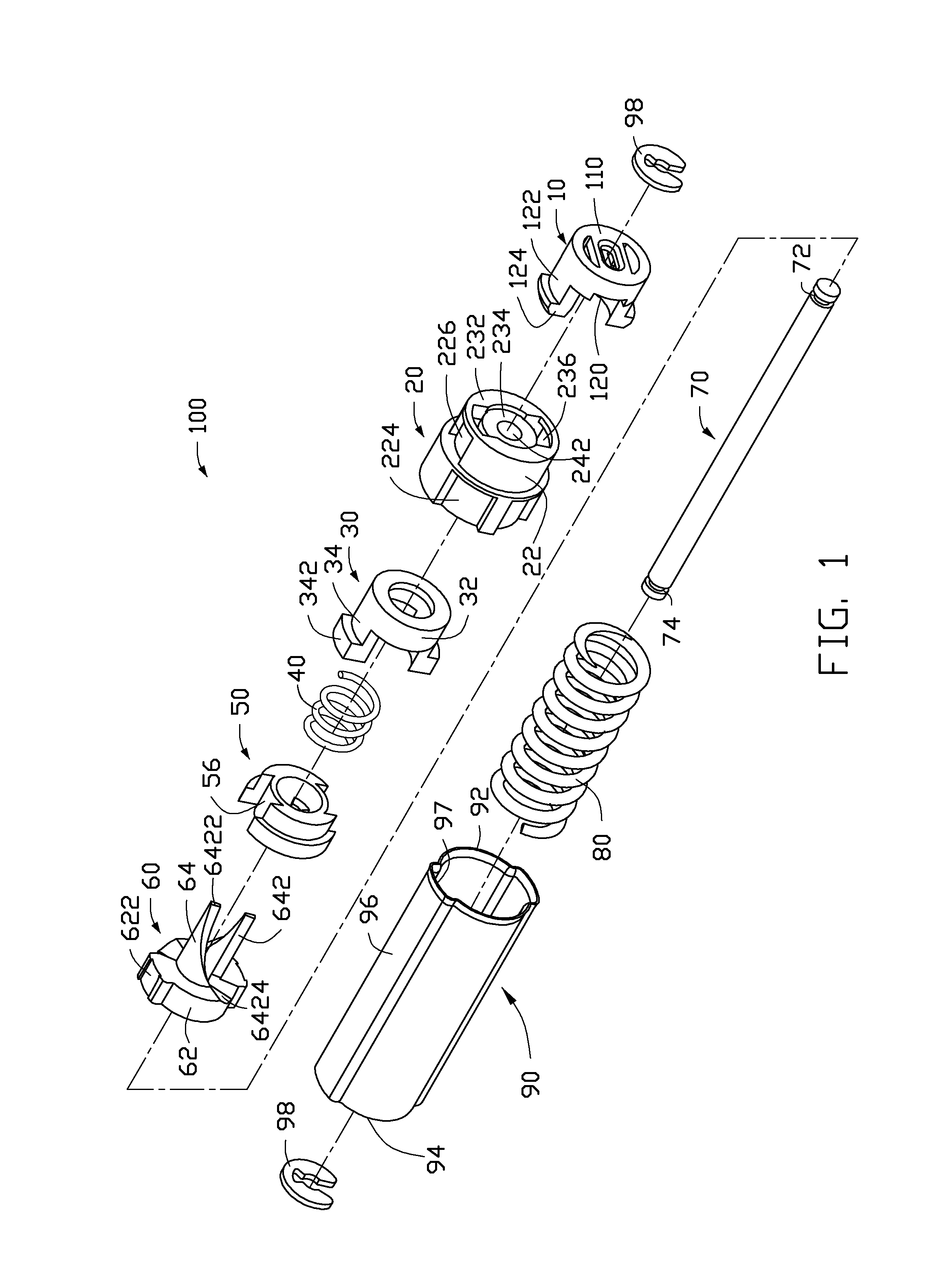
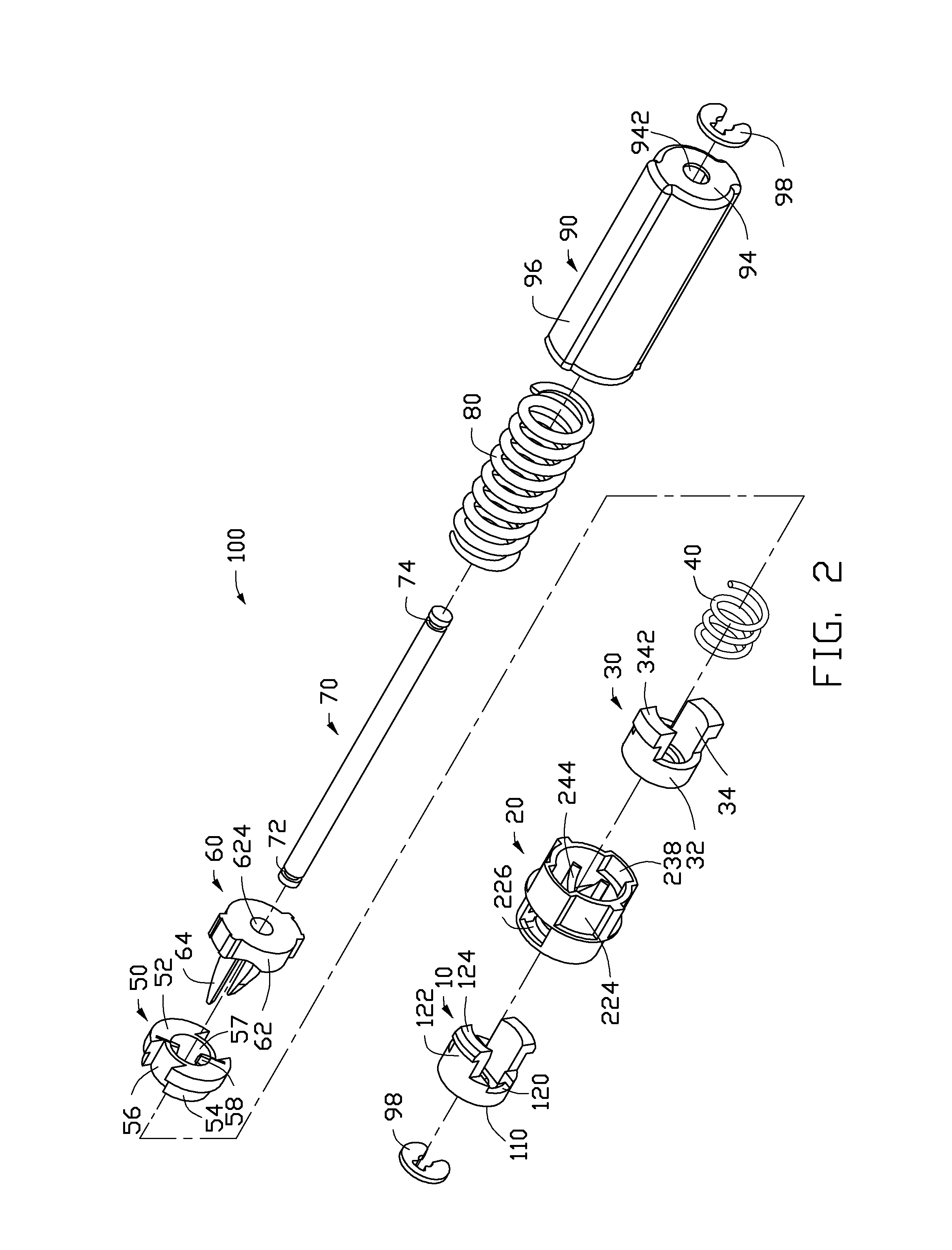
[0016]Referring to the drawings in detail, FIGS. 1 and 2 show a hinge assembly 100 applied in a foldable electronic device such as a flip type mobile phone. The hinge assembly 100 can be used in other environments (e.g. cabinet doors). Although used here in a foldable electronic device, the hinge assembly 100 should not be considered limited in scope solely to foldable electronic devices.

[0017]The hinge assembly 100, in the embodiment illustrated, includes a button 10, a receiving seat 20, a control member 30, a return elastic member 40, a clutch member 50, a follower 60, a shaft 70, a main elastic member 80, a sleeve 90, and two washers 98.

[0018]The button 10 is substantially cylindrical, and includes a pressed end 110 and an opposite open end 120. Two symmetric arms 122 are formed on the open end 120. A hook 124 extends from each arm 122. The button 10, when pressed, can press the control member 30 received in the receiving seat 20 so that the control member 30 is unlocked.

[0019]R...


PUM


Abstract

A hinge assembly includes a receiving seat, a control member, a clutch member, a follower, a main shaft and an elastic element. The receiving seat includes a first cam surface. The control member is releasably latched with the receiving seat. The clutch member includes at least one projection. The follower includes a second cam surface engaging with the at least one projection. The receiving seat, the control member, the clutch member and the follower are placed around the shaft. The elastic element provides an elastic force for the follower. After the control member is unlocked, the second cam surface engages with the first cam surface.

Description

BACKGROUND[0001]1. Technical Field[0002]The present disclosure relates to hinge assemblies and, particularly, to a spring-loaded hinge assembly for foldable devices such as portable telephones and portable computers that can activated by button.[0003]2. Description of Related Art[0004]Some hinge assemblies are spring-loaded and are used to assist in opening the foldable parts of mobile phones, which generally include a cover section and a body section. This kind of hinge assembly includes threaded engagement of its parts and is relatively complicate to manufacture. In addition, the threaded structure needs to be made of high strength material, which is costly.[0005]Therefore, there is room for improvement within the art.BRIEF DESCRIPTION OF THE DRAWINGS[0006]Many aspects of the embodiments can be better understood with references to the following drawings. The components in the drawings are not necessarily drawn to scale, the emphasis instead being placed upon clearly illustrating t...

Claims


Application Information

Patent Timeline
IPC IPC(8): H05K7/00E05D11/00E05F1/12
CPCH04M1/0216Y10T16/540255Y10T16/5398Y10T16/5387Y10T16/533
Inventor DUAN, CHAOCHEN, CHIA-HUA
Owner SHENZHEN FUTAIHONG PRECISION IND CO LTD
Why Eureka
Try Eureka