Piezoelectric pump

Active Publication Date: 2009-08-27
MURATA MFG CO LTD
View PDF14 Cites 11 Cited by
  • Summary
  • Abstract
  • Description
  • Claims
  • Application Information

AI Technical Summary

Benefits of technology

[0009]To overcome the problems described above, preferred embodiments of the present invention provide an efficient piezoelectric pump by eliminat

Problems solved by technology

When a neutral plane exists in the piezoelectric element, a portion of the piezoelectric element moves so as to resist bending, which causes a problem in that the displacement of the diaphragm unit is reduced and/or unwanted heat is generated.
On the other hand, with a diaphragm

Method used


Image

  • Piezoelectric pump
  • Piezoelectric pump
  • Piezoelectric pump

Examples


first preferred embodiment

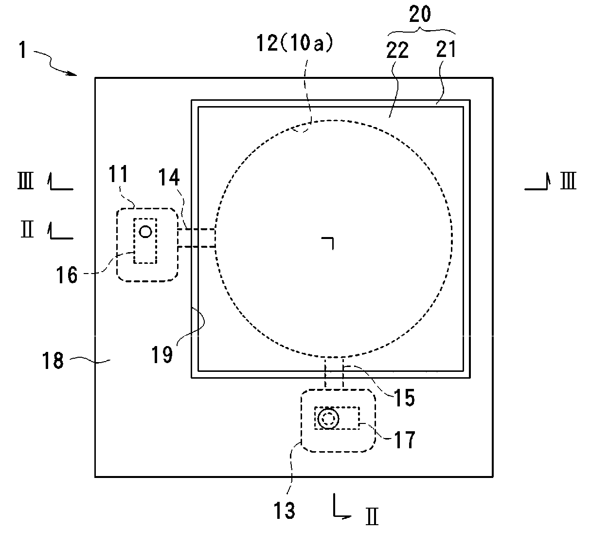
[0029]FIGS. 1 to 3 show a piezoelectric pump according to a first preferred embodiment of the present invention. FIG. 1 is a plan view of a piezoelectric pump; FIG. 2 is a sectional view taken along line II-II of FIG. 1; and FIG. 3 is a sectional view taken along line III-III of FIG. 1.

[0030]A piezoelectric pump 1 preferably includes a pump body 10, a diaphragm unit 20 including a piezoelectric element 22 that is bonded to a diaphragm 21, and a press plate 18. The pump body 10 is preferably made of a high-rigidity material, such as a metal or a resin, for example. A pump chamber 12 is defined between the pump body 10 and the diaphragm unit 20. Between the pump body 10 and the press plate 18, an input valve chamber 11, which communicates with the pump chamber 12 via a connection channel 14, and an output valve chamber 13, which communicates with the pump chamber 12 via a connection channel 15, are provided. An input check valve 16 is disposed in the input valve chamber 11. The input ...

second preferred embodiment

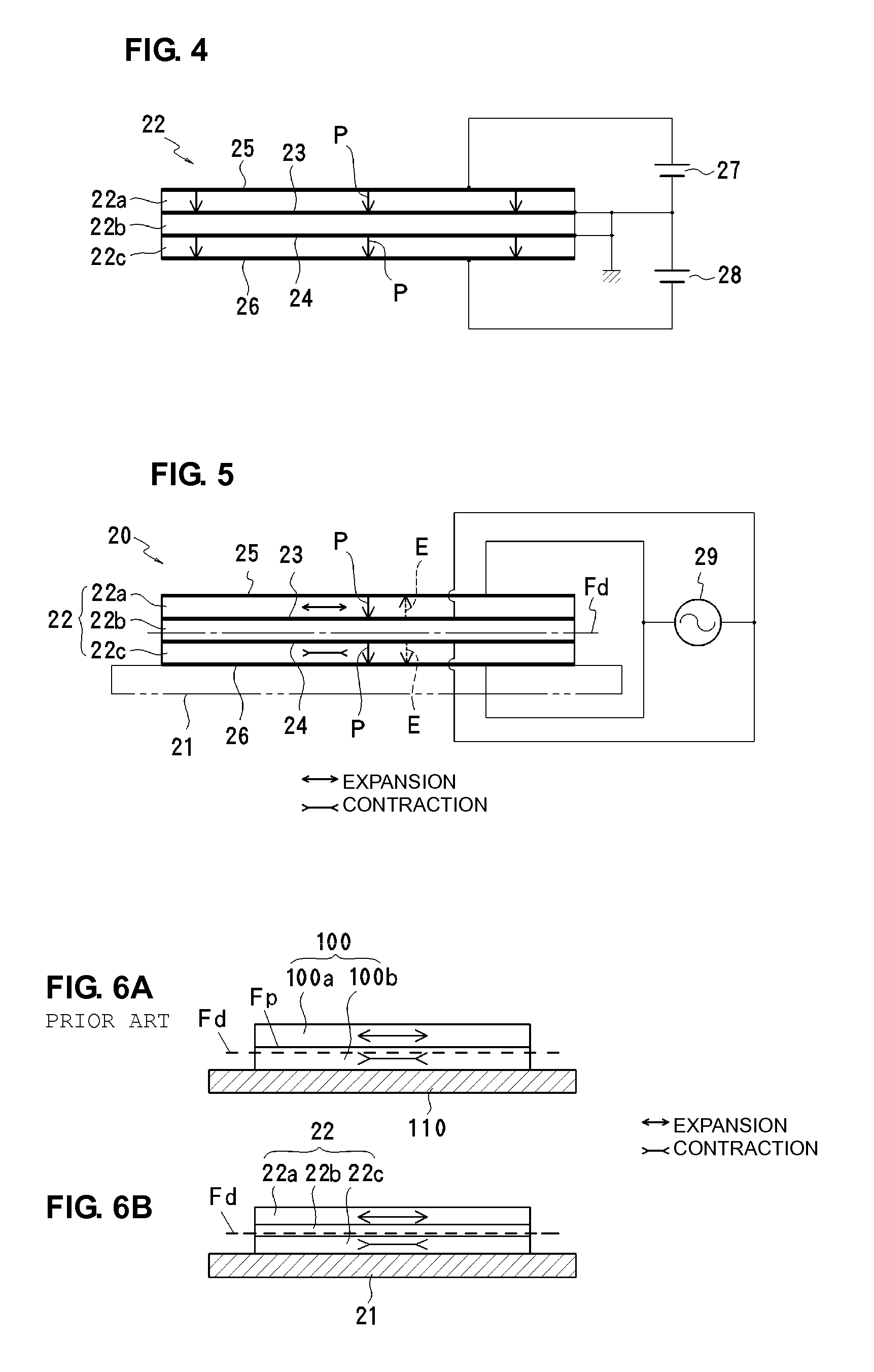
[0040]FIGS. 7 and 8 show a second preferred embodiment of the present invention. FIG. 7 shows a state in which a piezoelectric element 30 is being polarized, and FIG. 8 shows a state in which the diaphragm unit is being driven. In the second preferred embodiment, the piezoelectric element 30 includes a stack of eight piezoelectric layers 31a to 31h, preferably including two neutral piezoelectric layers 31d and 31e in the approximate middle in the thickness direction, for example. Although no electrodes are disposed between the neutral layers 31d and 31e in the second preferred embodiment, the electrodes may be disposed therebetween. The piezoelectric element 30 is bonded onto a diaphragm 34.

[0041]As shown in FIG. 7, in order to polarize the piezoelectric element, two DC power sources 35 and 36 are connected in series, the positive terminal of the DC power source 35 is connected to electrodes 33b and 33d, the negative terminal of the DC power source 36 is connected to electrodes 33e ...

third preferred embodiment

[0044]FIG. 9 shows a diaphragm unit according to a third preferred embodiment of the present invention. The third preferred embodiment is a modification of the second preferred embodiment. A piezoelectric element 40 includes a stack of nine piezoelectric layers 41a to 41i, including two piezoelectric layers 41e and 41f in the approximate middle in the thickness direction. Although no electrodes are disposed between the neutral layers 41e and 41f in the present preferred embodiment, electrodes may be disposed therebetween. Electrodes 43a to 43i are disposed on the front and back surfaces of the piezoelectric element 40 and between the layers. The piezoelectric element 40 is bonded onto a diaphragm 44.

[0045]One terminal of an AC power source 42 is connected to the first electrode 43a, the third electrode 43c, the fifth electrode 43e, the sixth electrode 43f, and the eighth electrode 43h. The other terminal of the AC power source 42 is connected to the second electrode 43b, the fourth ...


PUM


Abstract

A piezoelectric pump includes a diaphragm that defines a pump chamber between the diaphragm and a pump body, and a piezoelectric element bonded to a surface of the diaphragm. The piezoelectric element is a bimorph piezoelectric element in which a plurality of piezoelectric layers are stacked, including a neutral layer disposed in the approximate middle of the piezoelectric element in the thickness direction and that is not displaced. The piezoelectric element can be efficiently displaced because a neutral plane of the diaphragm and the piezoelectric element bonded therein is located in the neutral layer.

Description

BACKGROUND OF THE INVENTION[0001]1. Field of the Invention[0002]The present invention relates to a piezoelectric pump preferably for use in transporting fluid by applying a voltage to a piezoelectric element in order to bend a diaphragm.[0003]2. Description of the Related Art[0004]Piezoelectric micro pumps are used, for example, as coolant supply pumps in small electronic appliances, such as notebook PCs or as fuel supply pumps in fuel cells. Piezoelectric micro pumps utilize diaphragms that bend when a voltage is applied to piezoelectric elements. Piezoelectric micro pumps have advantages in that they have simple structures, low-profile shapes, and low power-consumption properties.[0005]Conventionally, a diaphragm unit in a piezoelectric micro pump, which includes a diaphragm on which a piezoelectric element is bonded, typically has a unimorph structure, in which a single-layer piezoelectric element is bonded to the diaphragm, or a bimorph structure, in which a multilayer piezoelec...

Claims


Application Information

Patent Timeline
IPC IPC(8): F04B43/04
CPCF04B43/046H01L41/0973H01L41/042H01L41/083H10N30/802H10N30/50H10N30/2047
Inventor KANAI, SHUNGO
Owner MURATA MFG CO LTD
Why Eureka
Try Eureka