
Heat Sink For Distributing A Thermal Load

Active Publication Date: 2011-11-24
LENOVO GLOBAL TECH INT LTD
View PDF10 Cites 12 Cited by
  • Summary
  • Abstract
  • Description
  • Claims
  • Application Information

AI Technical Summary

Benefits of technology

[0006]The foregoing and other objects, features and advantages of the invention will be apparent from the following more particular descriptions of exemplary embodimen

Problems solved by technology

Operating these computer processors requires a significant amount of power, and often such processors can consume over 100 watts.
Consuming significant amounts of power generates a considerable amount of heat.
Unless the heat is removed, heat generated by a computer processor may degrade or destroy the processor's functionality.

Method used


Image

  • Heat Sink For Distributing A Thermal Load
  • Heat Sink For Distributing A Thermal Load
  • Heat Sink For Distributing A Thermal Load

Examples


Embodiment Construction

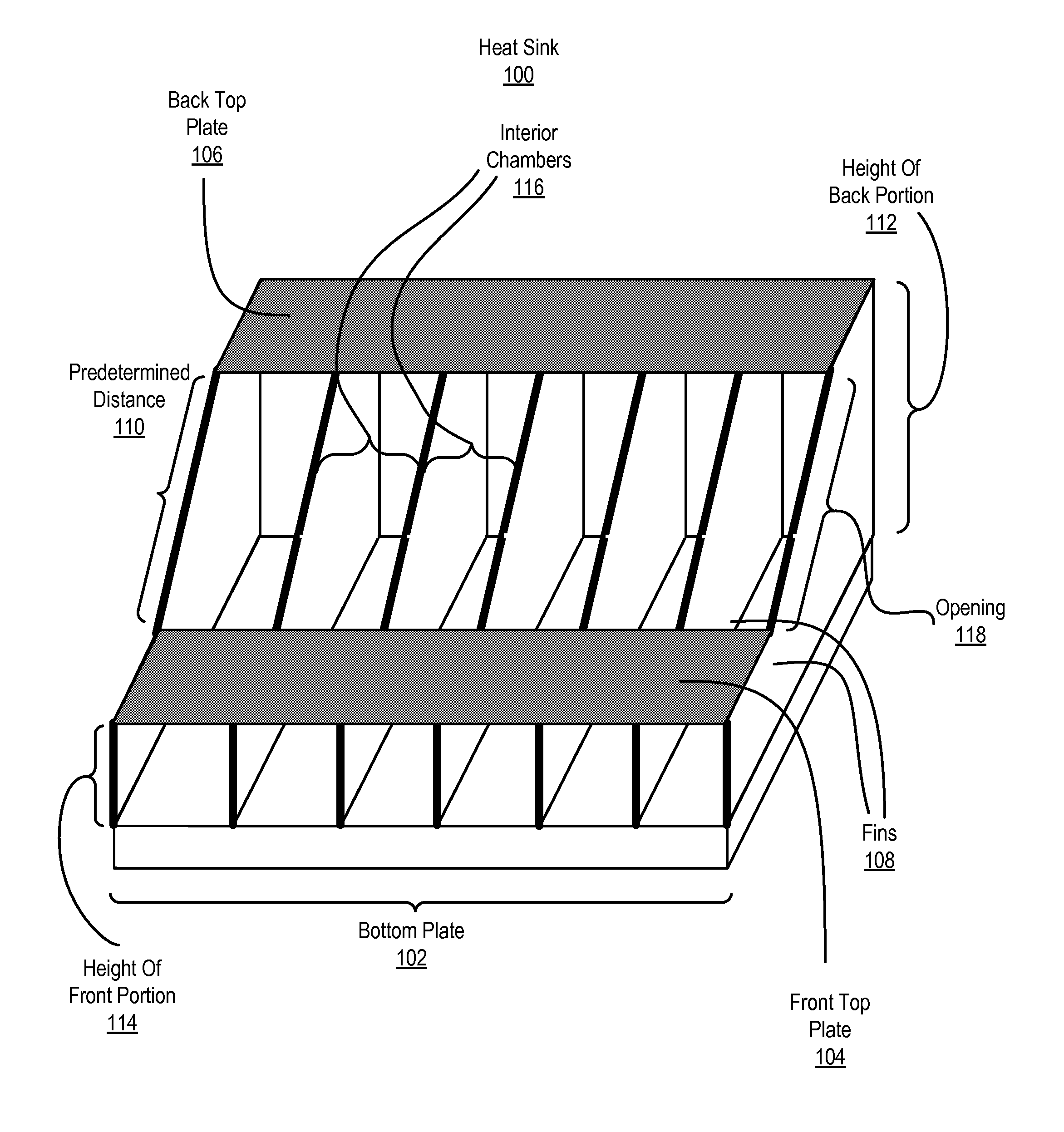
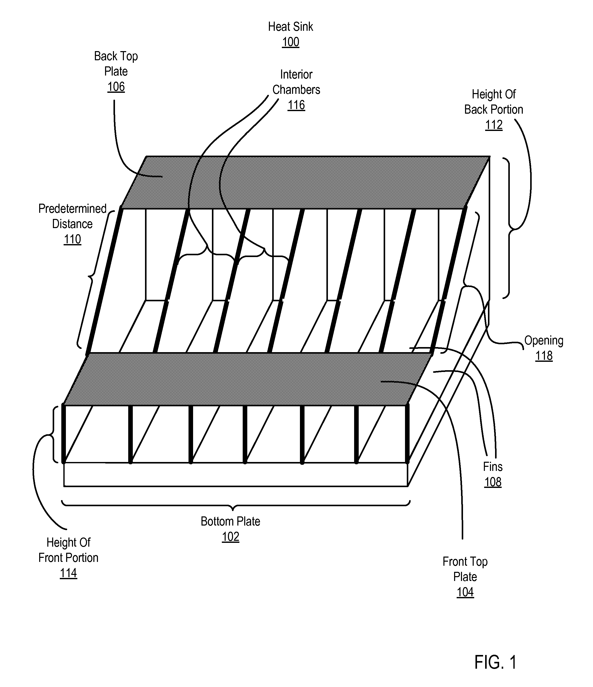
[0011]Exemplary methods, apparatus, and heat sinks for distributing a thermal load in accordance with the present invention are described with reference to the accompanying drawings, beginning with FIG. 1. FIG. 1 sets forth a perspective view of a heat sink (100) for distributing a thermal load according to embodiments of the present invention. The thermal load is the rate of thermal energy produced over time from the operation of an integrated circuit package (not shown) such as, for example, a computer processor or memory chip and is typically expressed in units of Watts.

[0012]In the example of FIG. 1, the heat sink (100) is a thermal conductor configured to absorb and dissipate the thermal load from an integrated circuit package thermally connected with the heat sink (100). Thermal conductors used in designing the heat sink (100) may include, for example, aluminum, copper, silver, aluminum silicon carbide, or carbon-based composites. The heat sink (100) of FIG. 1 may absorb the t...


PUM


Abstract

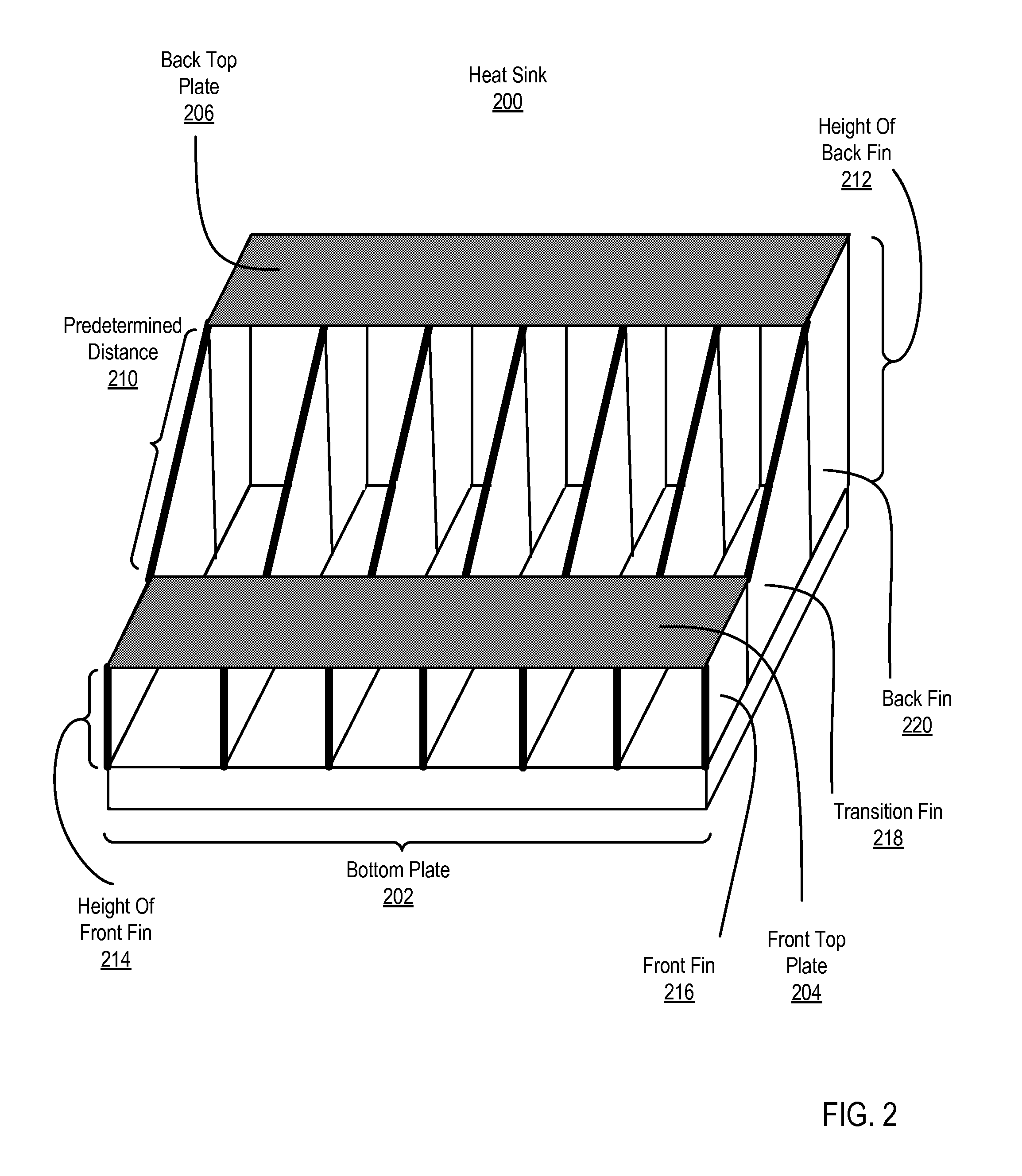
Heat sinks for distributing a thermal load are disclosed that include: a bottom plate; a front top plate; a back top plate; and a plurality of heat-dissipating fins connected to the bottom plate, the front top plate, and the back top plate, wherein the front top plate and the back top plate are separated by a predetermined distance.

Description

BACKGROUND OF THE INVENTION[0001]1. Field of the Invention[0002]The field of the invention is heat sinks for distributing a thermal load, including methods and apparatus that make use of heat sinks for distributing a thermal load.[0003]2. Description of Related Art[0004]Modern computer systems typically include a combination of hardware and software components, application programs, operating systems, processors, buses, memory, input / output devices, and so on. In order to deliver powerful computing resources, computer system designers must design powerful computer processors. Current computer processors, for example, are capable of executing billions of computer program instructions per second. Operating these computer processors requires a significant amount of power, and often such processors can consume over 100 watts. Consuming significant amounts of power generates a considerable amount of heat. Unless the heat is removed, heat generated by a computer processor may degrade or d...

Claims


Application Information

Patent Timeline
IPC IPC(8): G06F1/20F28F13/00F28F7/00
CPCF28F3/048F28F3/12G06F1/20H01L2924/0002H01L23/3672H01L2924/00
Inventor BRIDGES, JEREMY S.LA ROCCA, PAUL J.MEGARITY, WILLIAM M.
Owner LENOVO GLOBAL TECH INT LTD
Features
  • Generate Ideas
  • Intellectual Property
  • Life Sciences
  • Materials
  • Tech Scout
  • Unparalleled Data Quality
  • Higher Quality Content
  • 60% Fewer Hallucinations
Learn More