
Electro-Active Focus and Zoom Systems

a technology of optical focus and zoom system, applied in the field of electroactive optical system, can solve the problems of shock and vibration, heavy weight, and bulky devices incorporating these conventional systems, and achieve the effect of avoiding shock and vibration, reducing weight, and reducing the risk of failur

Active Publication Date: 2011-12-01
E VISION SMART OPTICS INC
View PDF5 Cites 11 Cited by
  • Summary
  • Abstract
  • Description
  • Claims
  • Application Information

AI Technical Summary

Problems solved by technology

As a consequence, devices incorporating these conventional systems can be bulky, heavy and prone to failure due to particulate contamination.
Further, conventional optical focus systems and zoom systems can also be prone to failure from shock and vibration.

Method used


Image

  • Electro-Active Focus and Zoom Systems
  • Electro-Active Focus and Zoom Systems
  • Electro-Active Focus and Zoom Systems

Examples


Embodiment Construction

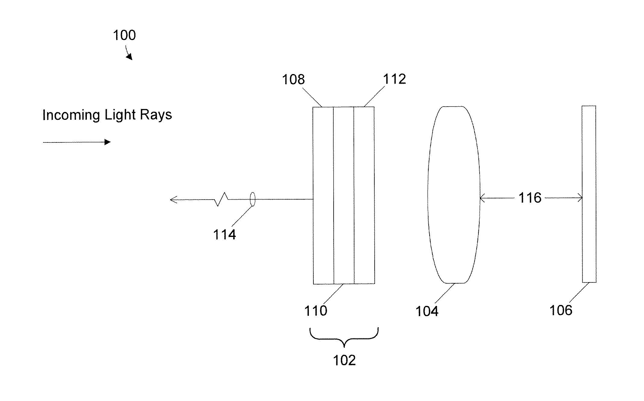
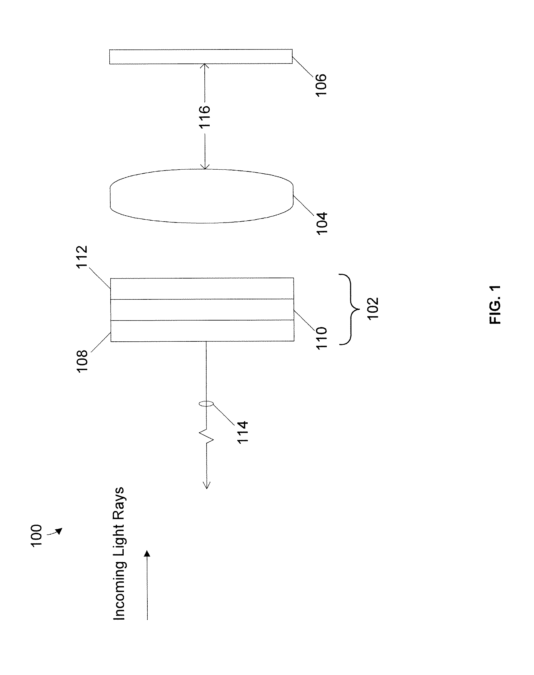
[0015]Aspects of the present invention provide dynamic focusing systems having no moving parts. For example, all lenses and focal planes, or a portion thereof, can be immobile along an optical axis in the dynamic focusing systems of the present invention. The dynamic focusing systems of the present invention can include an electro-active lens, a fixed focus lens in optical communication with the electro-active lens and a focal plane. The focal plane can be positioned to receive light focused by the combination of the electro-active lens and the fixed focus lens. The electro-active lenses of the present invention can have an adjustable optical power to provide variable focusing capability. The dynamic focusing systems of the present invention can include a controller for altering the adjustable optical power of the electro-active lens. The dynamic focusing systems of the present invention can focus on objects at various distances based on the controlled variable optical power of the ...


PUM


Abstract

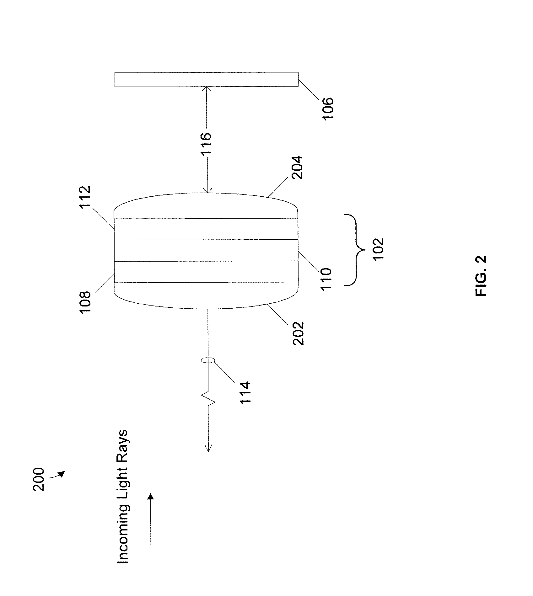
Aspects of the present invention provide dynamic focusing systems and dynamic zoom systems having no moving parts. The dynamic focusing systems can include an electro-active lens, a fixed focus lens in optical communication with the electro-active lens and a focal plane. The dynamic zoom systems can include a first electro-active lens, a second electro-active lens, a fixed focus lens, and a focal plane. The electro-active lenses of the present invention can have an adjustable optical power to provide variable focusing capability. The dynamic focusing systems and dynamic zoom systems can include a controller for altering the adjustable optical powers of the electro-active lenses. The dynamic focusing systems can focus on objects at various distances based on the controlled optical power of the included electro-active lenses. The dynamic zoom systems can provide magnification and de-magnification based on the controlled optical power of the included electro-active lenses.

Description

CROSS-REFERENCE TO RELATED APPLICATIONS[0001]This application claims priority from and incorporates by reference in their entirety the following provisional applications:[0002]U.S. Appl. No. 61 / 144,796, filed on Jan. 15, 2009; and[0003]U.S. Appl. No. 61 / 225,065, filed on Jul. 13, 2009.BACKGROUND OF THE INVENTION[0004]1. Field of the Invention[0005]The present invention generally relates to electro-active optical systems. More specifically, the present invention provides improved electro-active optical systems having dynamic focus and zoom capabilities.[0006]2. Background Art[0007]Conventional optical focus systems and optical zoom systems require moving parts. As a consequence, devices incorporating these conventional systems can be bulky, heavy and prone to failure due to particulate contamination. Further, conventional optical focus systems and zoom systems can also be prone to failure from shock and vibration.[0008]Accordingly, what are needed are improved optical focus systems a...

Claims


Application Information

Patent Timeline
Patent Type & Authority Applications(United States)
IPC IPC(8): H04N5/335
CPCG02B3/14G02B13/005G02B13/006G02F2001/294G02B13/008G02B13/009G02B13/0075G02F1/294
Inventor DUSTON, DWIGHTVAN HEUGTEN, ANTHONY
Owner E VISION SMART OPTICS INC
Learn More