Bread slicing apparatus

Active Publication Date: 2011-12-08
OSHIKIRIKK
View PDF7 Cites 0 Cited by
  • Summary
  • Abstract
  • Description
  • Claims
  • Application Information

AI Technical Summary

Benefits of technology

[0009]The present invention is provided to address the above situation. That is, the purpose of the present invention is to provide a bread slicing apparatus that can

Problems solved by technology

Since the conventional loaf bread slicer has the side frames, the arm members supported by the rotation shaft, and the pivot shafts for swinging the arm members, it takes a lot of trouble in detaching and attaching the endless blades.
As described above, in the

Method used


Image

  • Bread slicing apparatus
  • Bread slicing apparatus
  • Bread slicing apparatus

Examples


Embodiment Construction

[0021]Preferred embodiments of the present invention will now be described in detail in accordance with the accompanying drawings.

[0022]While the present invention has been described with reference to exemplary embodiments, it is to be understood that the invention is not limited to the disclosed exemplary embodiments. The scope of the following claims is to be accorded the broadest interpretation so as to encompass all such modifications and equivalent structures and functions.

[0023]By referring to the drawings, below will be described a loaf bread slicing apparatus of an embodiment where a bread slicing apparatus according to the present invention is applied.

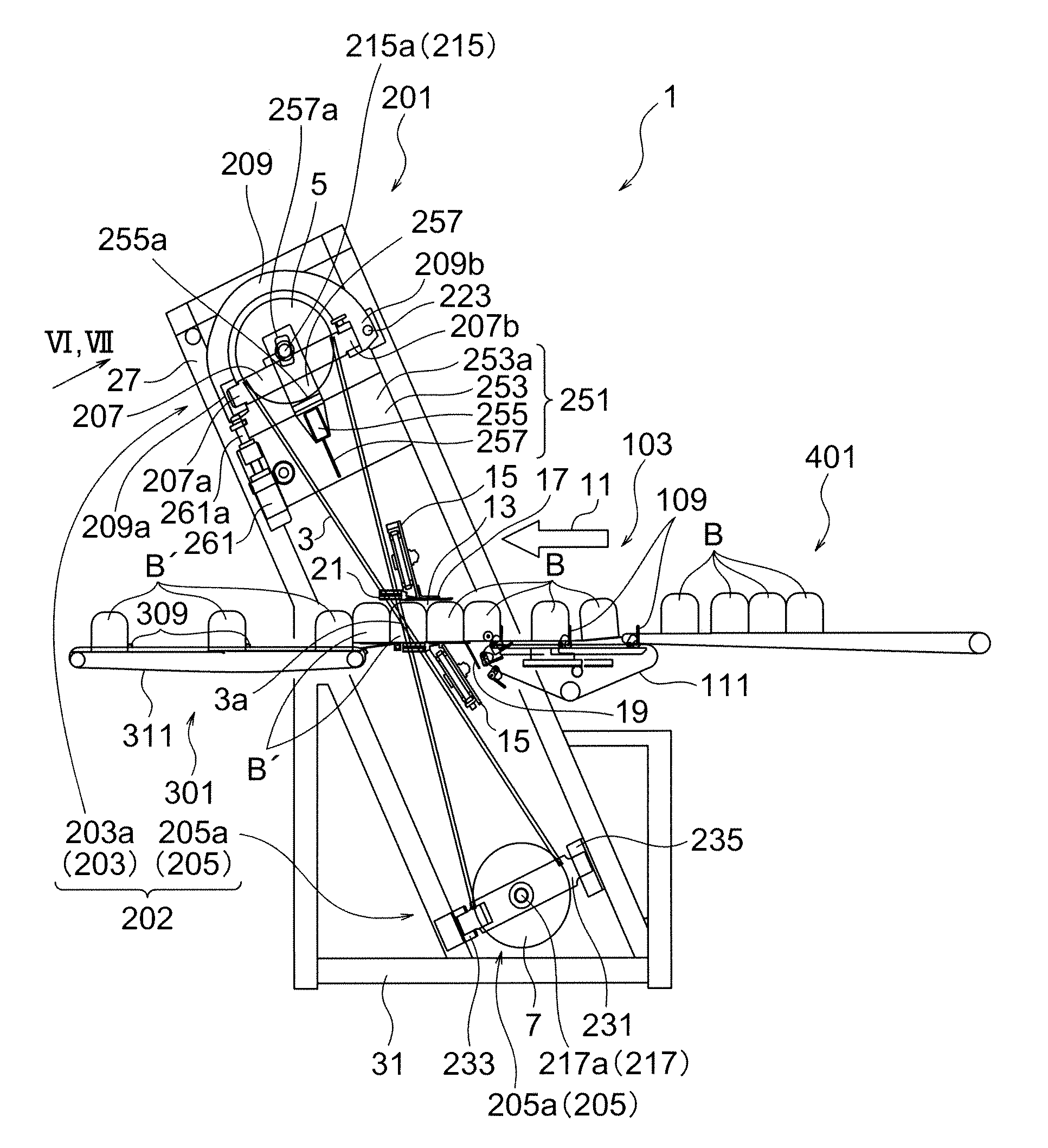
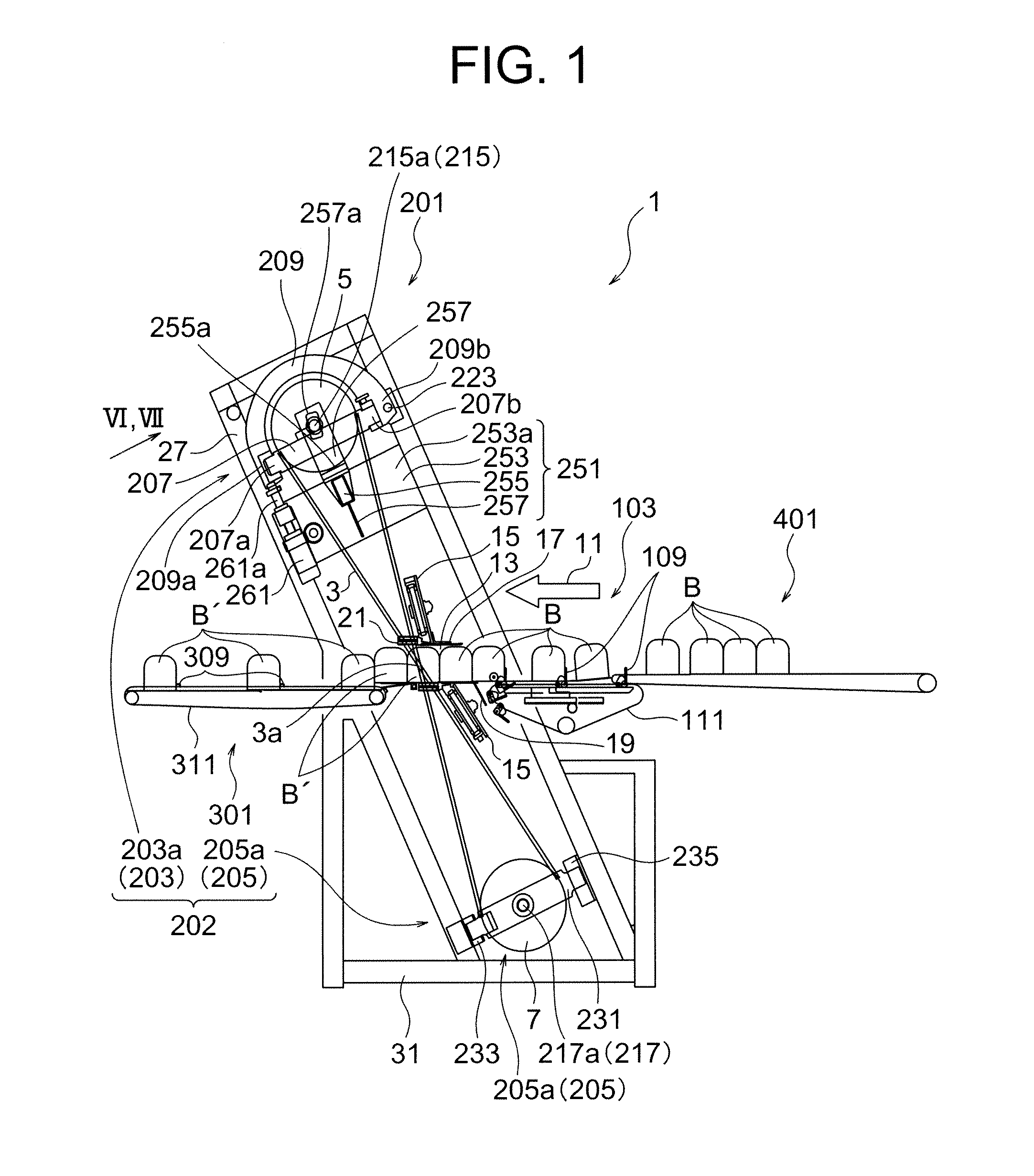
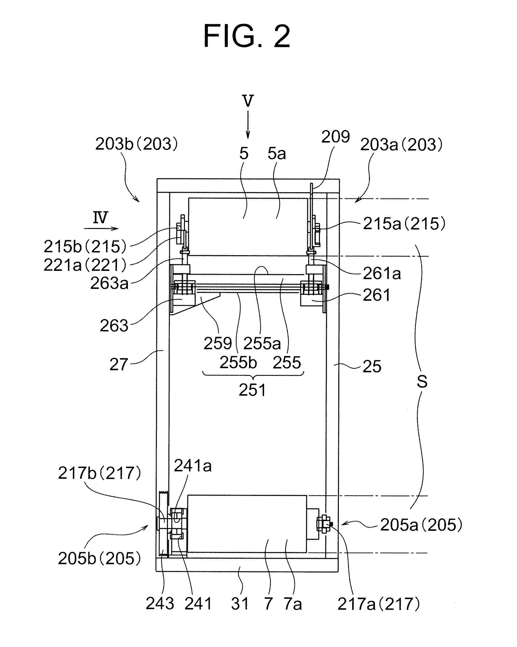
[0024]FIG. 1 is a side view that schematically shows the primary components of a loaf bread slicing apparatus 1 according to the embodiment; FIG. 2 is a front view of the loaf bread slicing apparatus 1 of FIG. 1; FIG. 3 is a side view showing an upper-right and a lower-right bread slicing drum support members 203a and 205a whe...


PUM

PropertyMeasurementUnit
Radiusaaaaaaaaaa

Abstract

A bread slicing apparatus comprises: a plurality of drums disposed spaced apart from each other and adapted to be wound with an endless blade; a plurality of rotation shafts on which the plurality of drums are coaxially mounted, respectively; a shaft support frame member extending outside a cylindrical space defined by an outer circumference surface and its extending surface of the plurality of drums; a shaft support member including one end portion pivotably mounted on the shaft support frame member and another end portion removably mounted on the shaft support frame member, and the shaft support member being capable of supporting at least one end portion of the plurality of rotation shafts; and a drum placement mechanism capable of placing at least one of the plurality of drums thereon, wherein the shaft support member is capable of pivoting between inside of the cylindrical space and outside of the cylindrical space, and the shaft support member is capable of pivoting toward the outside of the cylindrical space when the at least one of the plurality of drums is placed on the drum placement mechanism.

Description

BACKGROUND OF THE INVENTION[0001]1. Field of the Invention[0002]The present invention relates to a bread slicing apparatus for slicing the bread. In particular, the present invention relates to a bread slicing apparatus that can facilitate attachment and detachment of endless blades.[0003]2. Description of the Related Art[0004]Loaf bread slicing apparatuses for slicing the loaf bread have been conventionally used. For example, U.S. Pat. No. 2,795,254 discloses a loaf bread slicer in which both ends in the axial direction of a rotation shaft to which a drum is mounted are supported by a double end-supported beam frame. The conventional loaf bread slicer comprises a pair of drums, a frame supporting the rotation shafts of both drums so that both drums can rotate in parallel to each other, and a plurality of endless blades that are wound diagonally across both drums disposed in parallel.[0005]This frame is of a double end-supported beam type that comprises a pair of side frames extendi...

Claims


Application Information

Patent Timeline
IPC IPC(8): B26D1/46
CPCB26D7/2614B26D2007/327B26D1/48B26D1/50B26D2210/06B26D7/32Y10T83/707Y10T83/7183
Inventor OKI, YUZURUUMETSU, MASAMIHASEGAWA, TAKAHIRO
Owner OSHIKIRIKK
Why Eureka
Try Eureka