LED light bulbs

a technology of led light bulbs and led light tubes, which is applied in the manufacture of electrode systems, lighting support devices, gas-filled discharge tubes, etc., can solve the problems of generating significant amounts of heat that must be dissipated, and affecting the widespread implementation of led light bulbs

Active Publication Date: 2011-12-08
IDEAL IND LIGHTING LLC
View PDF3 Cites 219 Cited by
  • Summary
  • Abstract
  • Description
  • Claims
  • Application Information

AI Technical Summary

Benefits of technology

[0007]The present invention relates to improved LED light bulbs that address various limitations associated with known LED light bulbs.

Problems solved by technology

High power LEDs can draw large currents, thereby generating significant amounts of heat that must be dissipated.
It would be desirable to provide a LED light bulb capable of replacing an incandescent bulb without sacrificing light output characteristics, but various limitations have hindered widespread implementation of LED light bulbs.
One limitation that has limited widespread implementation of LED light bulbs includes fabrication cost, since assembly of numerous portions of conventional LED light bulbs typically entails assembly by hand—such as to make mechanical, electrical, and thermal (heat transfer) connections.
Another limitation associated with conventional LED light bulbs includes limited directional light output.
Unfortunately, a heatsink of sufficient size to dissipate the quantity of heat generated by the LED(s) tends to block output of light proximate to the base of the bulb.
When such a bulb is placed pointing upward in a table lamp, the resulting low intensity of light output in an area below the bulb and shadows are not pleasing to many users.

Method used


Image

  • LED light bulbs
  • LED light bulbs
  • LED light bulbs

Examples


Embodiment Construction

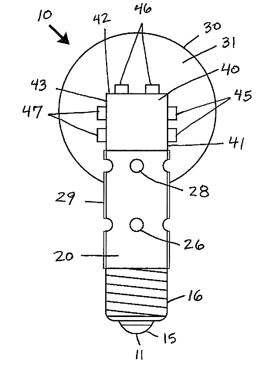
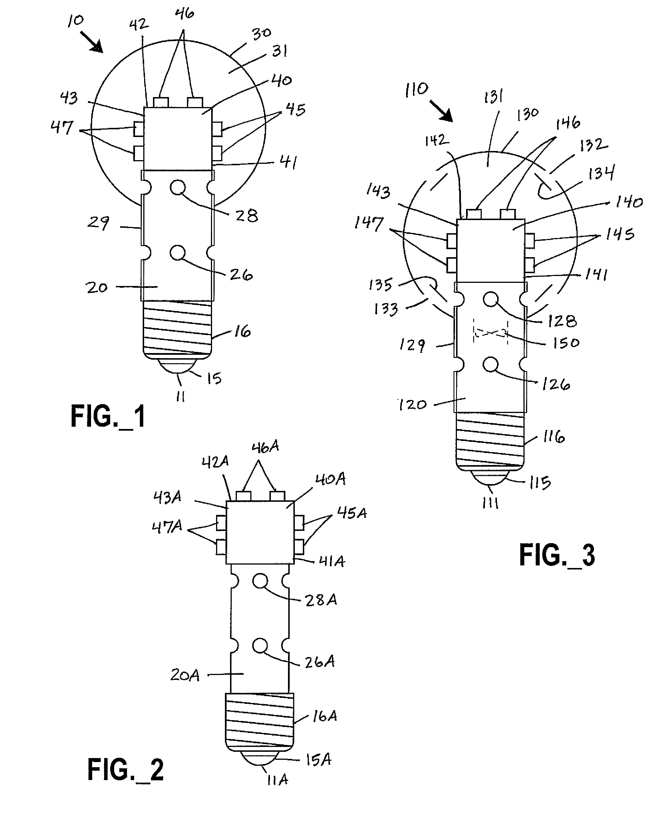
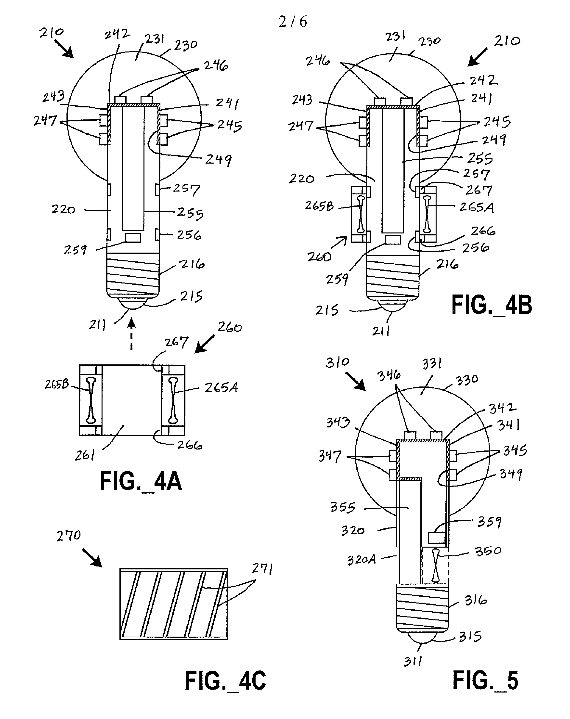
[0034]The present invention now will be described more fully hereinafter with reference to the accompanying drawings, in which embodiments of the invention are shown. The present invention may, however, be embodied in many different forms and should not be construed as limited to the specific embodiments set forth herein. Rather, these embodiments are provided to convey the scope of the invention to those skilled in the art. In the drawings, the size and relative sizes of layers and regions may be exaggerated for clarity.

[0035]Unless otherwise defined, terms (including technical and scientific terms) used herein should be construed to have the same meaning as commonly understood by one of ordinary skill in the art to which this invention belongs. It will be further understood that terms used herein should be interpreted as having a meaning that is consistent with their meaning in the context of this specification and the relevant art, and should not be interpreted in an idealized or...


PUM

PropertyMeasurementUnit
visible spectrum transmittanceaaaaaaaaaa
transmittanceaaaaaaaaaa
temperatureaaaaaaaaaa

Abstract

LED light bulbs include openings in base or cover portions, and optional forced flow elements, for convective cooling. Thermally conductive optically transmissive material may be used for cooling, optionally including fins. A LED light engine may be fabricated from a substrate via planar fabrication techiques and shaped to form a substantially rigid upright support structure. Mechanical, electrical, and thermal connections may be made between a LED light engine and a LED light bulb.

Description

FIELD OF THE INVENTION[0001]The present invention relates to solid state lighting devices, including light bulbs with one or more light emitting diodes.DESCRIPTION OF THE RELATED ART[0002]Light emitting diodes (LEDs) are solid state devices that convert electric energy to light, and generally include one or more active layers of semiconductor material sandwiched between oppositely doped layers. When bias is applied across doped layers, holes and electrons are injected into one or more active layers where they recombine to generate light that is emitted from the device. Laser diodes are solid state emitters that operate according to similar principles.[0003]Solid state light sources may be utilized to provide colored (e.g., non-white) or white LED light (e.g., perceived as being white or near-white). White solid state emitters have been investigated as potential replacements for white incandescent lamps. A representative example of a white LED lamp includes a package of a blue LED ch...

Claims


Application Information

Patent Timeline
Patent Type & Authority Applications(United States)
IPC IPC(8): H01K1/62H01J1/62H01K1/28H01K1/30H01J61/52H01J9/24
CPCF21Y2111/005Y10T29/4913H05K2201/047H05K2201/10106F21K9/135F21V23/005F21V23/02F21V29/006F21Y2101/02F21Y2105/001Y10S362/80F21V3/0463F21K9/56F21V3/0481F21K9/50F21K9/90F21V29/004F21V29/02F21V29/506F21V29/507F21V29/677F21V29/74F21V29/83F21Y2111/007F21V19/001F21V23/06F21K9/232F21K9/238F21K9/64F21V3/08F21V3/12F21V29/70F21Y2105/10F21Y2107/30F21Y2107/40F21Y2115/10F21Y2115/30F21K9/23F21K9/60F21V3/049F21V29/51F21V29/57
Inventor BRANDES, GEORGE R.GARCERAN, JULIO A.
Owner IDEAL IND LIGHTING LLC
Why Eureka
Try Eureka