
Terminal device, display method, and application computer program product

a technology of display method and terminal device, which is applied in the direction of static indicating device, portable computer details, instruments, etc., can solve the problems of shortening the working time of the battery and increasing the power consumption of the terminal device, so as to reduce the power consumption and reduce the power consumption

Inactive Publication Date: 2011-12-08
SONY CORP +1
View PDF3 Cites 41 Cited by
  • Summary
  • Abstract
  • Description
  • Claims
  • Application Information

AI Technical Summary

Benefits of technology

The technical effect of this patent is that if a user looks at just one part of a screen, only that portion will have its own separate display with less energy usage compared to showing everything on both screens simultaneously. However, if the user wants to look at both parts equally, then they will get full-screen displays on both sides, allowing them to see more content while saving battery power.

Problems solved by technology

The technical problem addressed by this patent is how to improve the functionality and visual experience of terminal devices with multiple display units, including but not limited to mobile phones, e-readers, and gaming consoles.

Method used


Image

  • Terminal device, display method, and application computer program product
  • Terminal device, display method, and application computer program product
  • Terminal device, display method, and application computer program product

Examples


Embodiment Construction

[0024]An embodiment of the present invention will be described in the following order.

[0025]1. description of terminal device (FIG. 1 to FIG. 3)

[0026]2. description of control of display change (FIG. 4 to FIG. 8B)

[0027]3. description of first modification (FIG. 9)

[0028]4. description of second modification (FIGS. 10A and 103)

[0029]5. other modifications

[1. Description of Terminal Device]

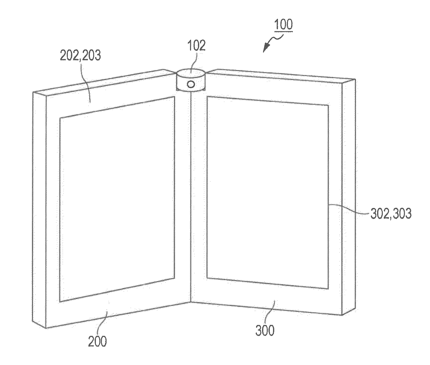
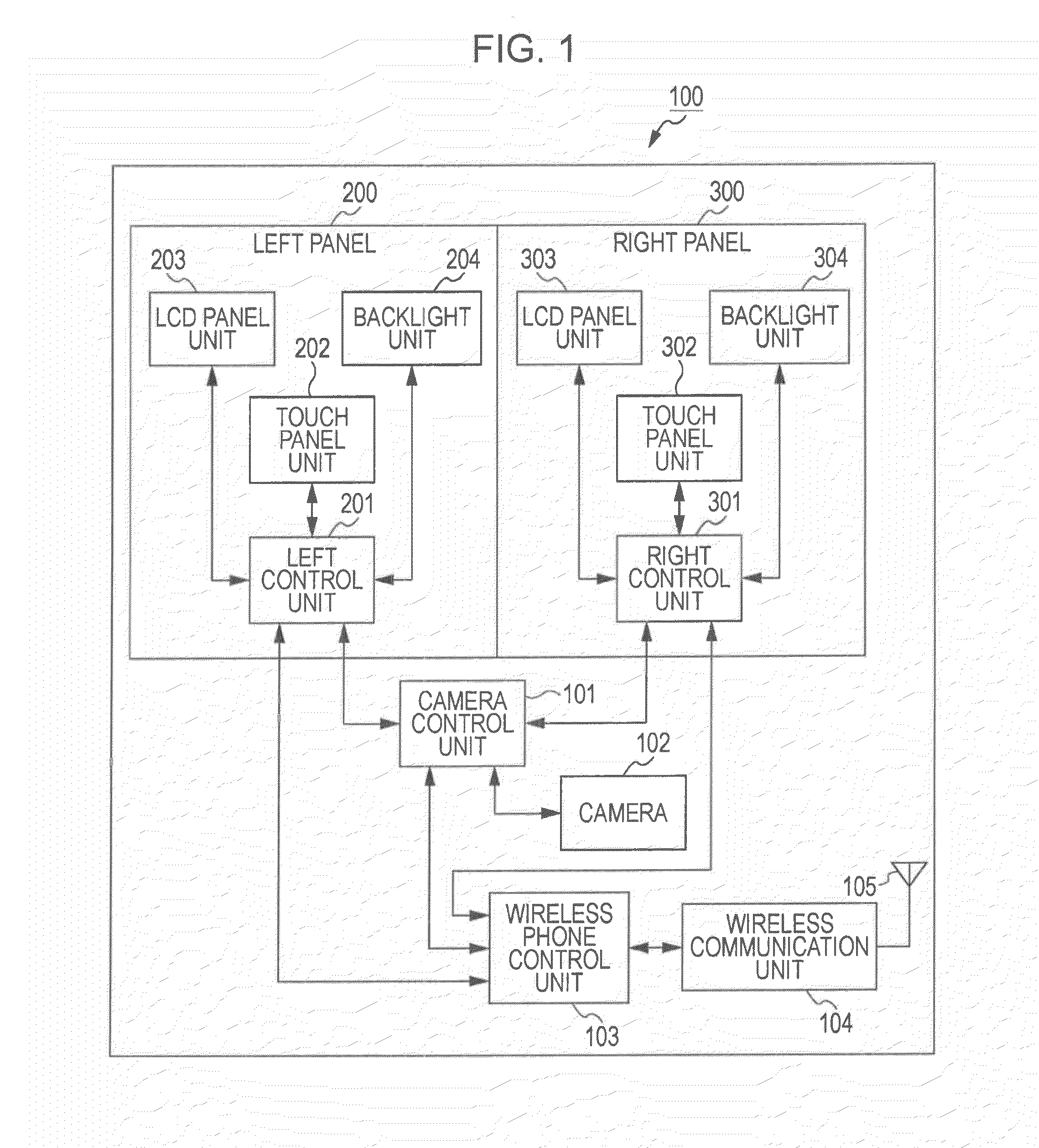
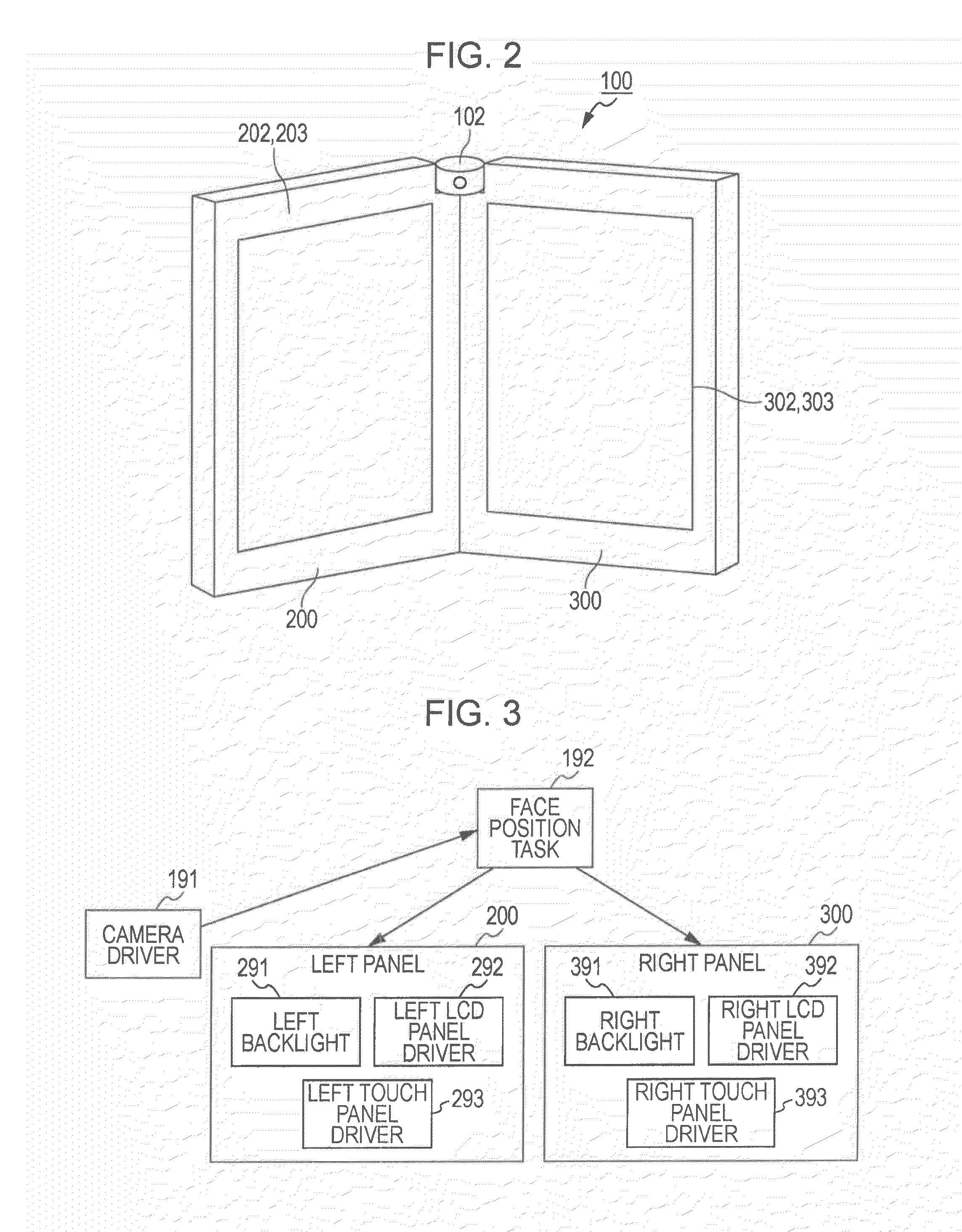
[0030]FIG. 1 illustrates an example of a configuration of a terminal device 100 according to an embodiment of the present invention. FIG. 2 illustrates an example of an appearance of the terminal device 100.

[0031]As illustrated in FIG. 2, the terminal device 100 includes a left panel 200 and a right panel 300 composed of two casings which can be folded together. The terminal device 100 also has a camera 102 disposed at the fold between the left panel 200 and the right panel 300. The camera 102 picks up an image of a user facing the display panels. In the present embodiment, the camera 102 (or other t...


PUM


Abstract

A terminal device includes a display unit having at least a first display area and a second display area, a detection unit configured to detect a viewing state in which the first display area and/or the second display area are being viewed, and a control unit configured to, when a predetermined application is executed, perform control on the basis of the viewing state detected by the detection unit, for switching between a state in which display is performed on either one of the first display area and the second display area and display is not performed on the other one of the first display area and the second display area and a state in which display is performed on both the first display area and the second display area. A method and computer program storage device holding computer readable instructions cooperate to form a system that performs these functions.

Description


Claims


Application Information

Patent Timeline
Owner SONY CORP
Learn More