Cutting tool and cutting insert with fluid flow structures

a technology of cutting tools and inserts, which is applied in the direction of milling cutters, milling equipment, turning apparatuses, etc., can solve problems such as weakening inserts, and achieve the effects of facilitating fluid introduction, facilitating fluid introduction, and complicating insert manufactur

Active Publication Date: 2011-12-08
SECO TOOLS AB
View PDF20 Cites 44 Cited by
  • Summary
  • Abstract
  • Description
  • Claims
  • Application Information

AI Technical Summary

Benefits of technology

[0001]The present invention relates generally to cutting tools and cutting inserts and, more particularly, to such cutting tools and inserts having fluid flow channels. Conventional techniques for providing lubricating and / or cooling fluid to cutting edges of cutting inserts typically involve introducing the fluid via openings in a toolholder for the cutting insert, or via spray nozzles directed at the cutting edges. Some cutting inserts include channels formed in the inserts that are in flow communication with and facilitate introduction of fluid from channels provided in the toolholder body. The provision of these fluid flow channels in the cutting inserts tends to substantially complicate manufacture of the inserts, and the channels can weaken the insert. It is desirable to provide a cutting tool and cutting insert that facilitate introduction of fluid to the cutting edges of the insert that minimizes manufacturing complexity. It is also desirable to provide a cutting tool and cutting insert that facilitate introduction of fluid to the cutting edge without substantially interfering with the strength of the insert.

Problems solved by technology

The provision of these fluid flow channels in the cutting inserts tends to substantially complicate manufacture of the inserts, and the channels can weaken the insert.

Method used


Image

  • Cutting tool and cutting insert with fluid flow structures
  • Cutting tool and cutting insert with fluid flow structures
  • Cutting tool and cutting insert with fluid flow structures

Examples


Embodiment Construction

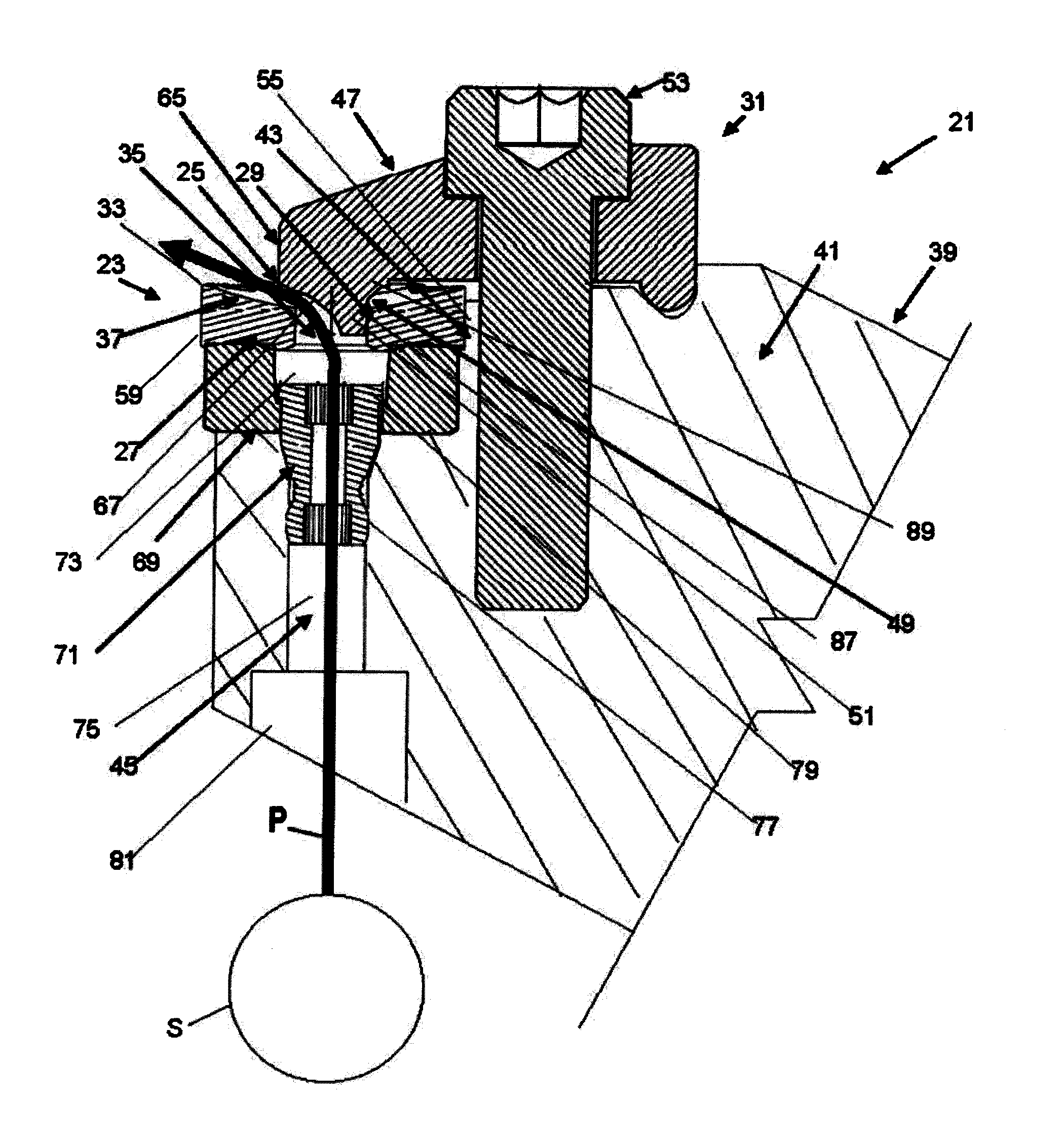
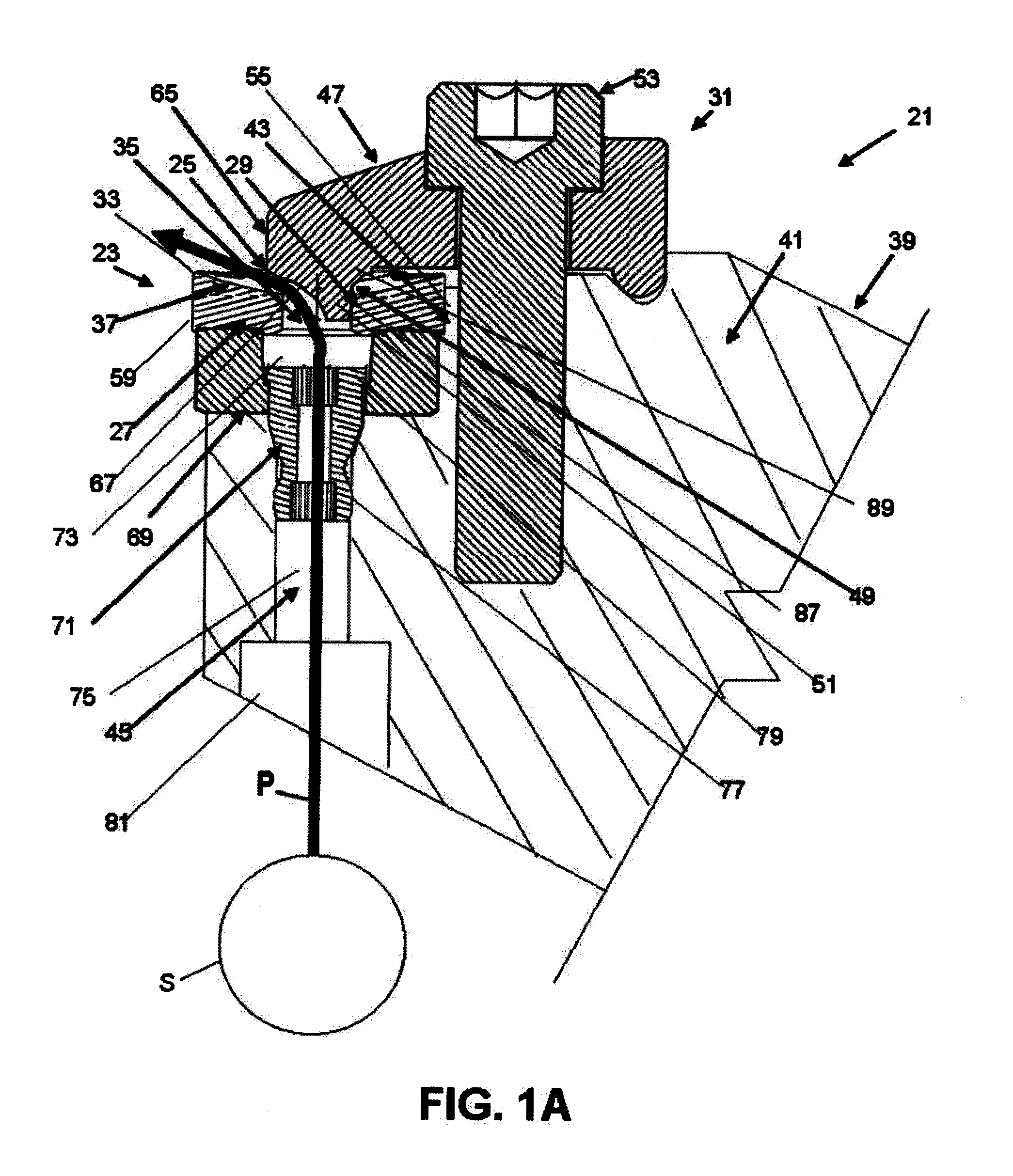
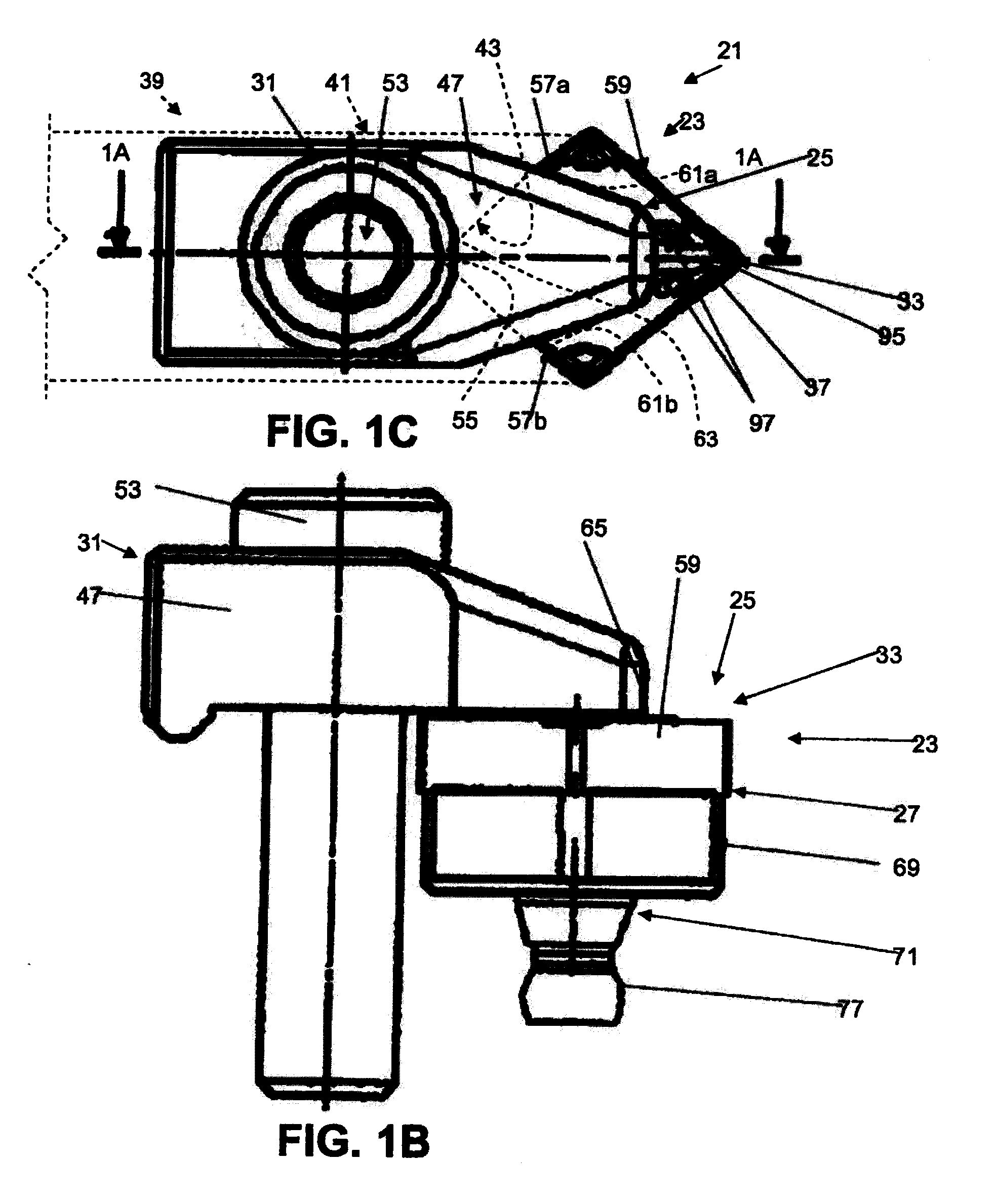
[0007]An illustrative cutting tool 21 according to an aspect of the present invention is shown in FIG. 1A. The cutting tool 21 comprises a cutting insert 23 comprising a top surface 25 and a bottom surface 27. The insert 23 also comprises a clamping surface 29 for abutting a clamp 31 and a cutting edge 33. A hole 35 extends through the insert 23 from the bottom surface 27 to the clamping surface 29. A channel 37 extends from the clamping surface 29 to point proximate and inward of the cutting edge 33.

[0008]The cutting tool 21 also comprises a toolholder 39 comprising a toolholder body 41 having a pocket 43 for receiving the insert 23. The toolholder 39 also comprises the clamp 31 for contacting the clamping surface 29 and clamping the insert in the pocket 43. The toolholder 39 also comprises a toolholder passage 45 in the body 41 in flow communication with the hole 35 in the insert 23. By providing the cutting tool 21 and cutting insert 23 with a fluid flow passage P extending from ...


PUM

PropertyMeasurementUnit
angleaaaaaaaaaa
diameteraaaaaaaaaa
lengthaaaaaaaaaa

Abstract

A cutting tool includes a cutting insert comprising a top surface, a bottom surface, a clamping surface for abutting a clamp, a cutting edge, a hole extending through the insert from the bottom surface to the clamping surface, and a channel extending from the clamping surface to proximate the cutting edge, and a tool holder comprising a tool holder body having a pocket for receiving the insert, a clamp for contacting the clamping surface and clamping the insert in the pocket, and a tool holder passage in the body in flow communication with the hole in the insert. A cutting insert is also provided.

Description

BACKGROUND AND SUMMARY[0001]The present invention relates generally to cutting tools and cutting inserts and, more particularly, to such cutting tools and inserts having fluid flow channels. Conventional techniques for providing lubricating and / or cooling fluid to cutting edges of cutting inserts typically involve introducing the fluid via openings in a toolholder for the cutting insert, or via spray nozzles directed at the cutting edges. Some cutting inserts include channels formed in the inserts that are in flow communication with and facilitate introduction of fluid from channels provided in the toolholder body. The provision of these fluid flow channels in the cutting inserts tends to substantially complicate manufacture of the inserts, and the channels can weaken the insert. It is desirable to provide a cutting tool and cutting insert that facilitate introduction of fluid to the cutting edges of the insert that minimizes manufacturing complexity. It is also desirable to provide...

Claims


Application Information

Patent Timeline
Patent Type & Authority Applications(United States)
IPC IPC(8): B23B27/10B23C5/20B23C5/28B23B27/16B23B27/22
CPCB23B27/10B23B27/1614B23B2200/086Y10T407/24Y10T407/14Y10T407/28Y10T407/235B23B2260/03Y10T407/245Y10T407/2282Y10T407/23B23C5/281B23C5/28
Inventor HOFERMANN, VOLKER
Owner SECO TOOLS AB
Why Eureka
Try Eureka