Utilizing a diluent to lower combustion instabilities in a gas turbine engine

a gas turbine engine and combustion dynamics technology, applied in the direction of machines/engines, mechanical equipment, lighting and heating apparatus, etc., can solve the problems of increasing fuel consumption, poor emissions, and difficult to predict the frequency at which combustion oscillations occur, so as to reduce combustion dynamics and reduce combustion dynamics

Active Publication Date: 2011-12-08
SIEMENS ENERGY INC
View PDF57 Cites 12 Cited by
  • Summary
  • Abstract
  • Description
  • Claims
  • Application Information

AI Technical Summary

Problems solved by technology

Since the structure of the combustor surrounding the combustion flame is often complicated, and varies from one combustor to another, and the combustion flame itself may vary over time, it is difficult to predict the frequency at which combustion os...

Method used


Image

  • Utilizing a diluent to lower combustion instabilities in a gas turbine engine
  • Utilizing a diluent to lower combustion instabilities in a gas turbine engine

Examples


Embodiment Construction

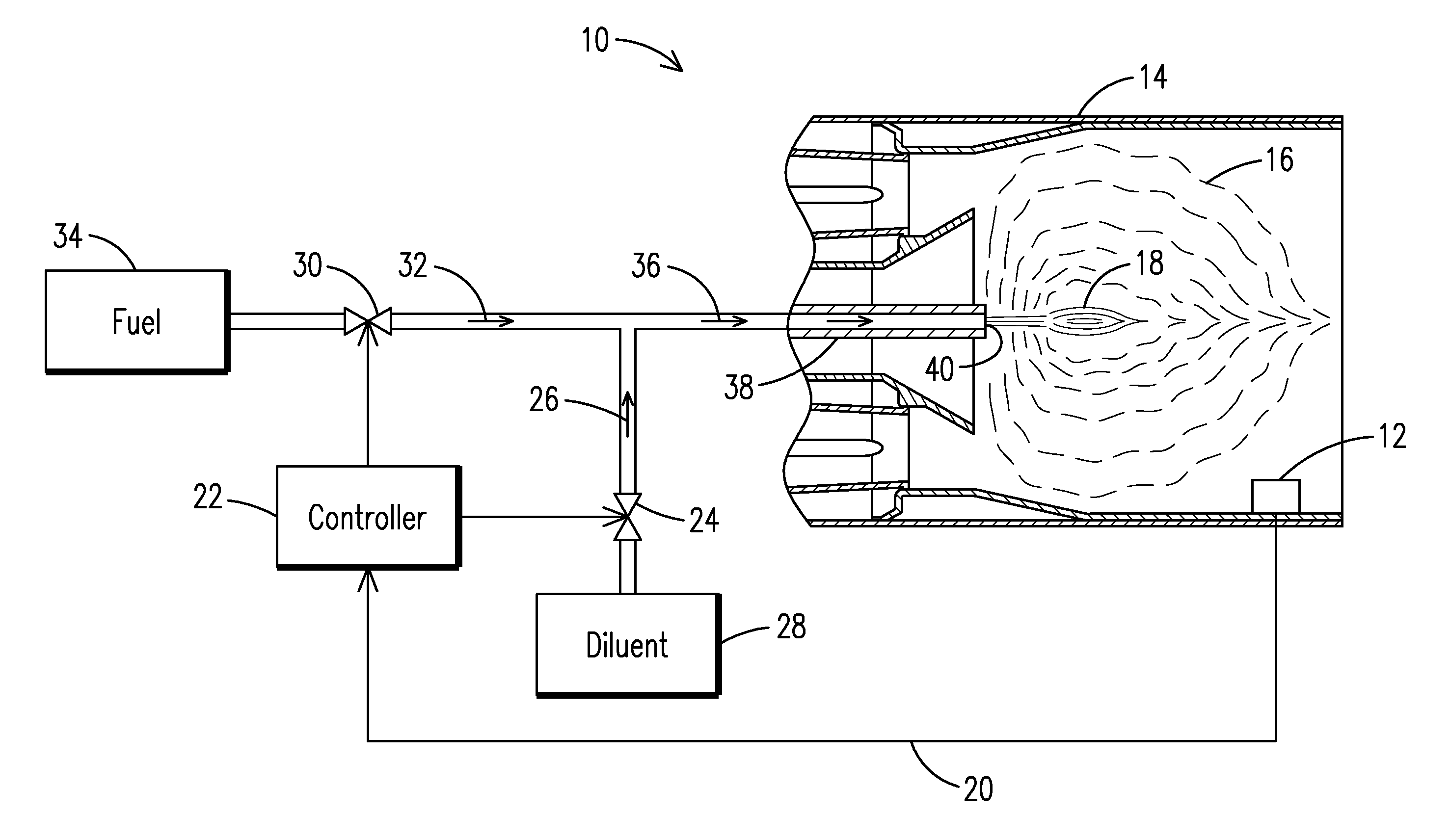
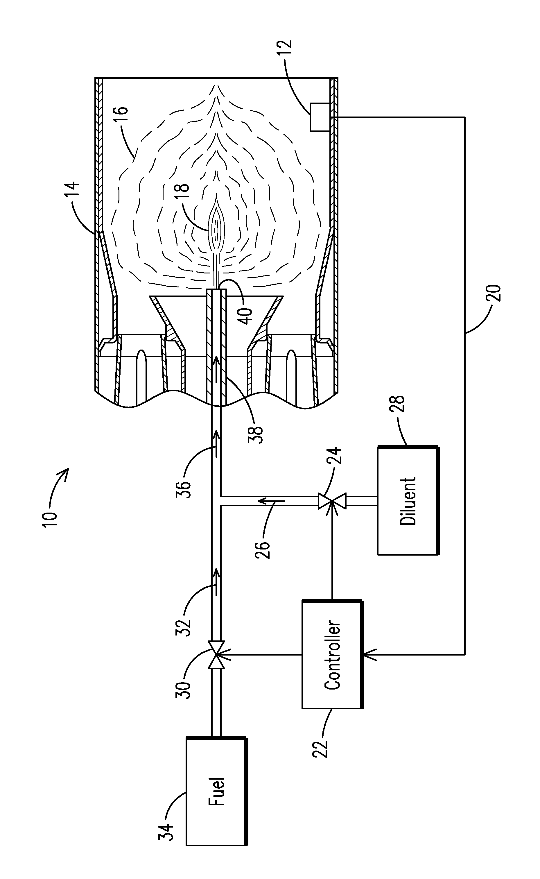
[0008]In the prior art, it is known to adjust the pilot flame of a burner by controlling the amount of fuel delivered to the pilot burner fuel outlet in order to affect the combustion dynamics of the burner. The present inventor has recognized that increasing the pilot fuel flow improves the stability of a combustion flame not only because it increases the energy of the pilot flame, but also because it changes the size, shape, and location of the pilot flame within the combustion flame. The present inventor has devised an alternative and innovative way to change the size, shape, and location of the pilot flame to influence the combustion flame and related combustion dynamics, and in an embodiment does so without changing the energy of the pilot flame. The method of the present invention avoids the drawbacks of the prior art, such as increased fuel consumption and increased unfavorable emissions associated with increased pilot flame energy, while still permitting sufficient influence...


PUM


Abstract

A method of influencing combustion dynamics, including measuring a combustion dynamics parameter, and controlling a diluent flow (26) delivered to a fuel flow (32) upstream of a pilot burner fuel outlet (40) in response to the measured combustion dynamics parameter.

Description

FIELD OF THE INVENTION[0001]The invention relates to controlling combustion dynamics in a gas turbine engine. More particularly, this invention relates to controlling combustion dynamics by controlling characteristics of the pilot flame in the gas turbine engine.BACKGROUND OF THE INVENTION[0002]Gas turbine engines are known to include a compressor for compressing air, a combustor for producing a hot gas by burning fuel in the presence of the compressed air produced by the compressor, and a turbine for expanding the hot gas to extract shaft power. Gas turbine engines using annular combustion systems typically include a plurality of individual burners disposed in a ring about an axial centerline for providing a mixture of fuel and air to an annular combustion chamber disposed upstream of the annular turbine inlet vanes. Other gas turbines use can-annular combustors wherein individual burner cans feed hot combustion gas into respective individual portions of the arc of the turbine inle...

Claims


Application Information

Patent Timeline
IPC IPC(8): F23C99/00
CPCF02C3/30F23K2301/103F23L2900/07003F23R2900/00013F23N5/16F23R3/28F23N1/082F23K2300/103
Inventor WASIF, SAMER P.
Owner SIEMENS ENERGY INC
Why Eureka
Try Eureka