Eureka AIR delivers breakthrough ideas for toughest innovation challenges, trusted by R&D personnel around the world.

Pressure Vessel Boss and Liner Interface

Active Publication Date: 2011-12-15
HEXAGON TECHNOLOGY AS
View PDF5 Cites 20 Cited by
  • Summary
  • Abstract
  • Description
  • Claims
  • Application Information

AI Technical Summary

Benefits of technology

This summary is provided to introduce concepts in simplified form that are further described below in the Detailed Description. This summary is not intended to identify key features or essential features of the disclosed or claimed subject matter and is not intended to describe each disclosed embodiment or every implementation of the disclosed or claimed subject matter. Specifically, features discl

Problems solved by technology

However, in high pressure (e.g., 700 bar) service, distortions of the plastic liner material adjacent the boss has been noted, leading to some tendency of the plastic to be pulled out of the keyway (i.e., out of the interlocking means 40).

Method used


Image

  • Pressure Vessel Boss and Liner Interface
  • Pressure Vessel Boss and Liner Interface
  • Pressure Vessel Boss and Liner Interface

Examples


Embodiment Construction

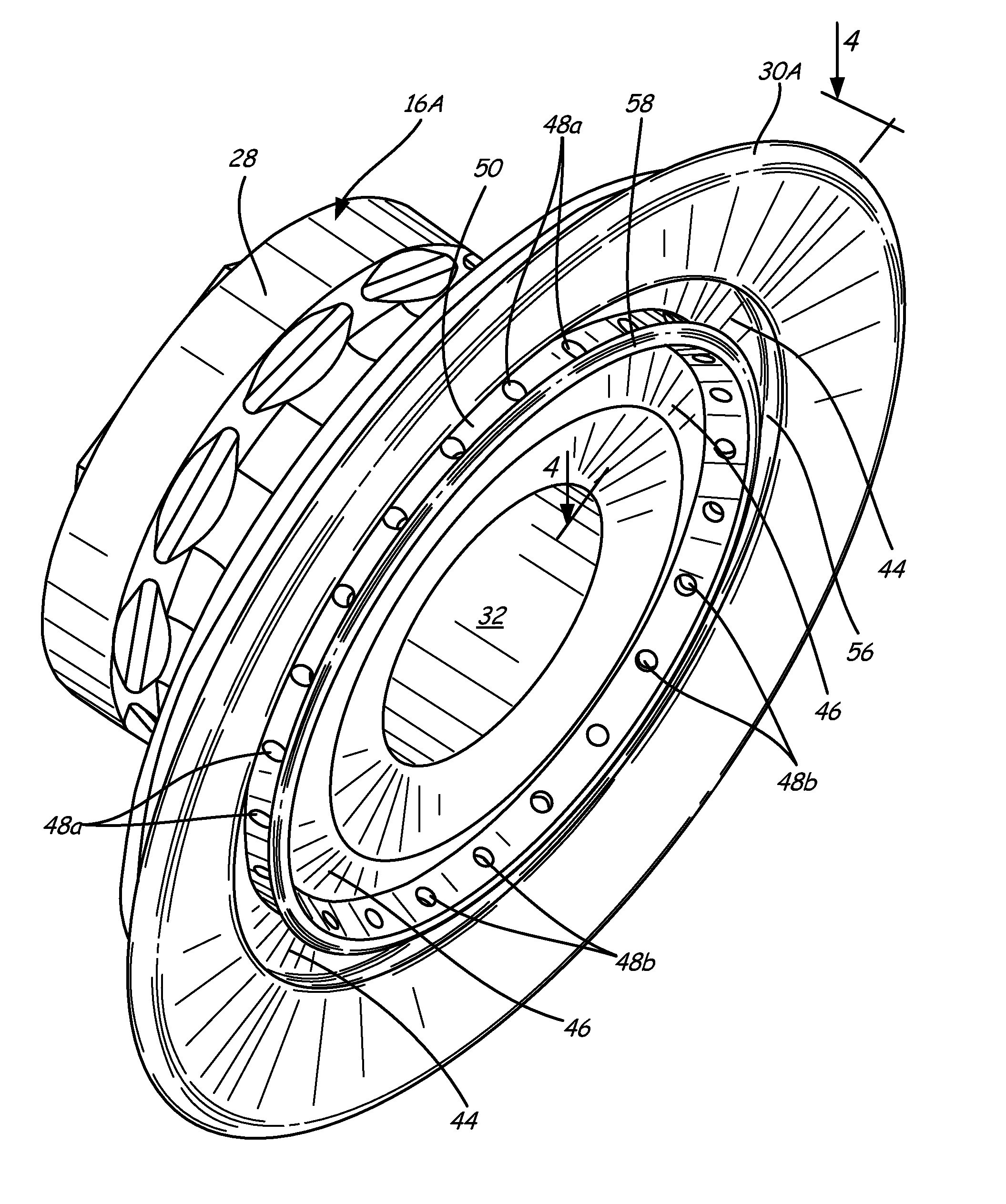
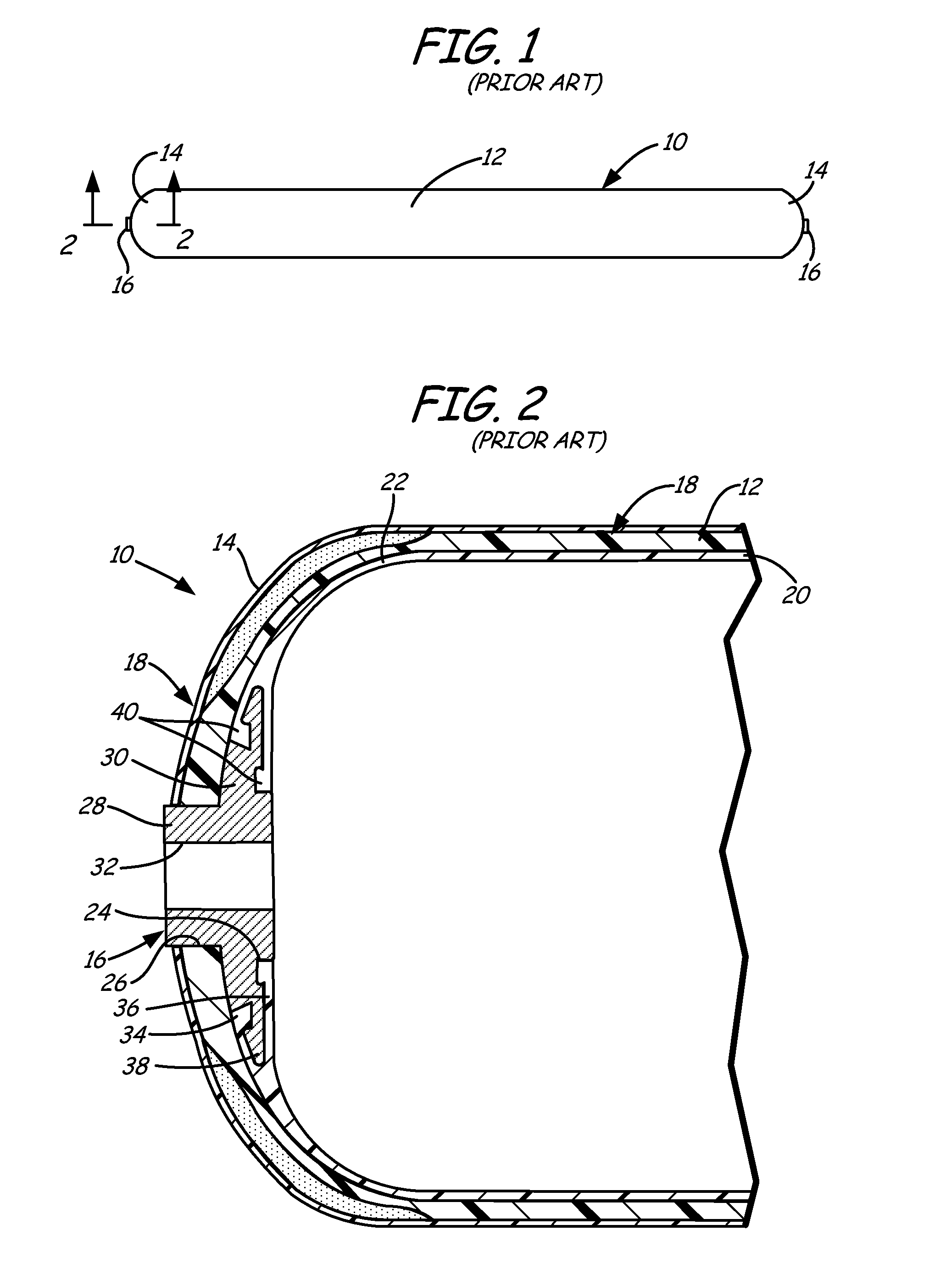
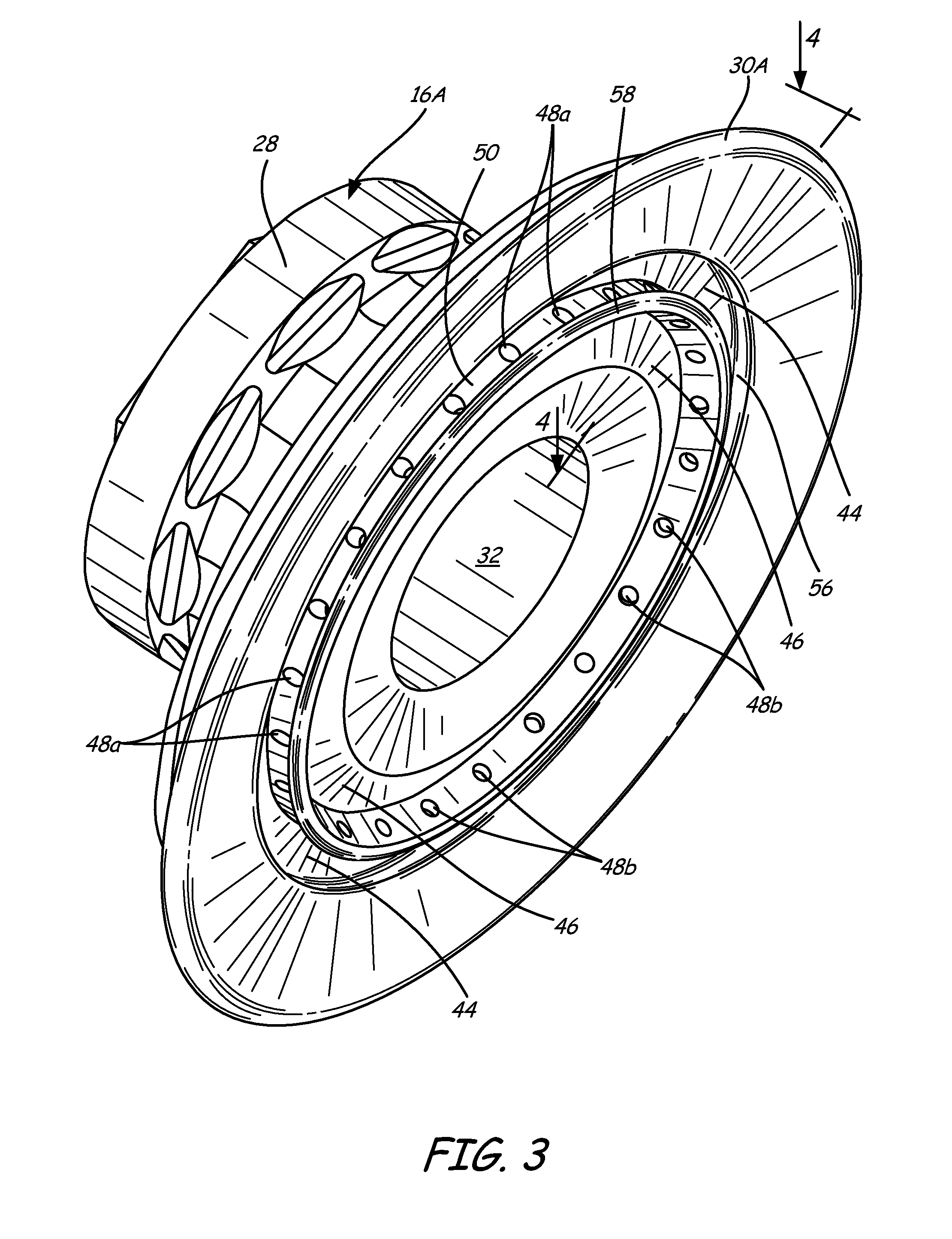
In one embodiment, an improved boss and liner interface structure is illustrated on boss 16A of FIGS. 3, 4A and 4B. Annular external or exterior keyway 42 and annular internal or interior keyway 44 are provided on flange 30 to mate with interlocking keys 42a and 44a of liner 20, respectively. As used in this disclosure, the term “dovetail” describes a keyway or interlocking key configuration comprising a lip, notch, flare, projection or similar or corresponding structure so that a joint formed between the keyway 42 / 44 of boss 16A and interlocking keys 42a / 44a of liner 20 is structurally inhibited from separation. External keyway 42 includes annular lip 52 extending in an axial direction to prevent separation in the radial direction and annular lip 54 extending in a radial direction to prevent separation in the axial direction. Similarly, internal keyway 44 includes annular lip 56 extending in an axial direction to prevent separation in the radial direction and annular lip 58 extendi...


PUM


Abstract

A boss for a pressure vessel has a flange. The flange includes an interior keyway having an inner sidewall and a plurality of bores disposed on the inner sidewall. A pressure vessel includes a main body section and an end section. The end section includes a boss and the boss includes a flange. The flange includes an interior keyway having an inner sidewall and a plurality of bores disposed on the inner sidewall. In another aspect, a pressure vessel includes an outer shell, and inner liner and a boss including a flange with an exterior side and an interior side. The liner is mechanically integrated with the flange via a plurality of anchors, each anchor contacting the flange only on the interior side. A method of forming a pressure vessel includes providing a boss having a flange. The flange has an interior keyway having an inner sidewall and a plurality of bores disposed on the inner sidewall. The method comprises allowing a fluid polymer material to flow into the interior keyway and into the plurality of bores.

Description

BACKGROUNDPressure vessels are commonly used for containing a variety of fluids under pressure, such as storing oxygen, natural gas, nitrogen, propane and other fuels, for example. Suitable container materials include laminated layers of wound fiberglass filaments or other synthetic filaments bonded together by a thermal-setting or thermoplastic resin. An elastomeric or other non-metal resilient liner or bladder often is disposed within the composite shell to seal the vessel and prevent internal fluids from contacting the composite material. The composite construction of the vessels provides numerous advantages such as lightness in weight and resistance to corrosion, fatigue and catastrophic failure. These attributes are due to the high specific strengths of the reinforcing fibers or filaments that are typically oriented in the direction of the principal forces in the construction of the pressure vessels.FIGS. 1 and 2 illustrate an elongated pressure vessel 10, such as that disclose...

Claims


Application Information

Patent Timeline
IPC IPC(8): F17C1/00B65D6/40B23P19/04
CPCF17C1/06Y10T29/49826F17C2201/0109F17C2201/056F17C2203/0604F17C2203/0619F17C2203/066F17C2203/0663F17C2203/0673F17C2205/0305F17C2221/011F17C2221/014F17C2221/033F17C2221/035F17C2223/0123F17C2223/036F17C2260/011F17C2260/036F17C1/16Y02E60/32F17C1/08B29D22/003F17C2209/22F17C2209/232B05D7/227
Inventor NEWHOUSE, NORMAN L.TILLER, DALE B.
Owner HEXAGON TECHNOLOGY AS
Why Eureka
Eureka Blog
Learn More