Piezoelectric foaming pump

a piezoelectric pump and foaming technology, applied in the field of piezoelectric pumps, can solve the problems of less than desirable surface coverage on the individual's skin, and achieve the effect of rapid piezoelectric element vibration

Inactive Publication Date: 2011-12-15
GOJO IND INC
View PDF15 Cites 15 Cited by
  • Summary
  • Abstract
  • Description
  • Claims
  • Application Information

AI Technical Summary

Benefits of technology

[0004]A piezoelectric foaming pump is provided herein. The piezoelectric foaming pump includes a housing having a first opening for receiving a liquid from a liquid container and a piezoelectric element secured to the housing. The piezoelectric element includes a plurality of holes there through. In addition, the housing includes an air inlet. Although the piezoelectric element has holes there through, prior to activating the piezoelectric element, liquid does not pass through the plurality of holes. When the piezoelectric element is energized, liquid passes through the plurality of holes due to the rapid vibration of the piezoelectric element and is dispensed as a foam. Additionally, a piezoelectric foaming pump having a fluid pump chamber; an air pump chamber; a mixing chamber; a piezoelectric element; and an outlet nozzle is disclosed herein. During operation, fluid pumped from the fluid chamber mixes with air pumped from an air chamber in the mixing chamber and the resulting mixture is passed through the piezoelectric element and dispensed out of a nozzle.

Problems solved by technology

Dispensed liquids may be difficult to spread resulting in less than desirable surface coverage on an individual's skin.
Unfortunately, this results in waste because many individuals dispense an excess amount of liquid sanitizer to facilitate spreading the liquid over the surface of their skin.

Method used


Image

  • Piezoelectric foaming pump
  • Piezoelectric foaming pump
  • Piezoelectric foaming pump

Examples


Embodiment Construction

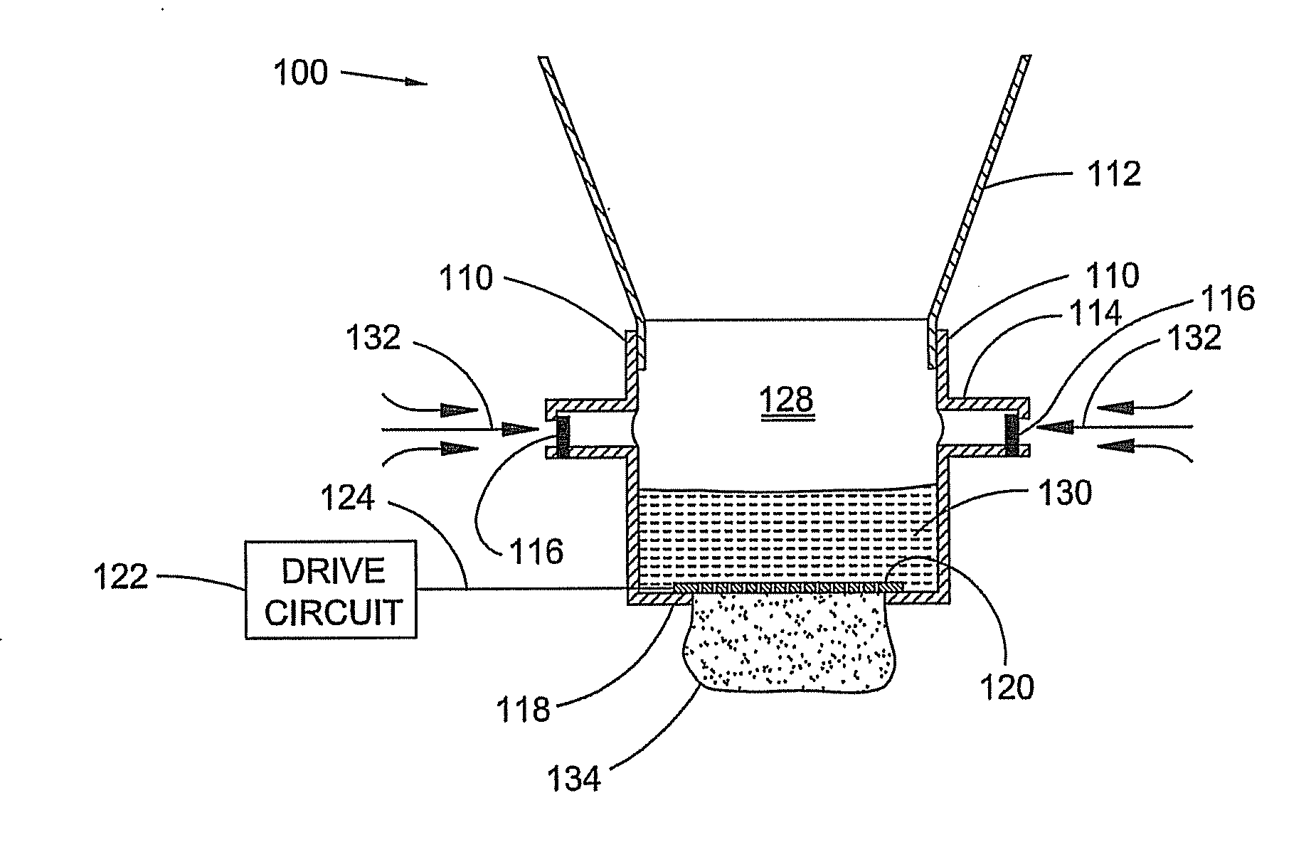
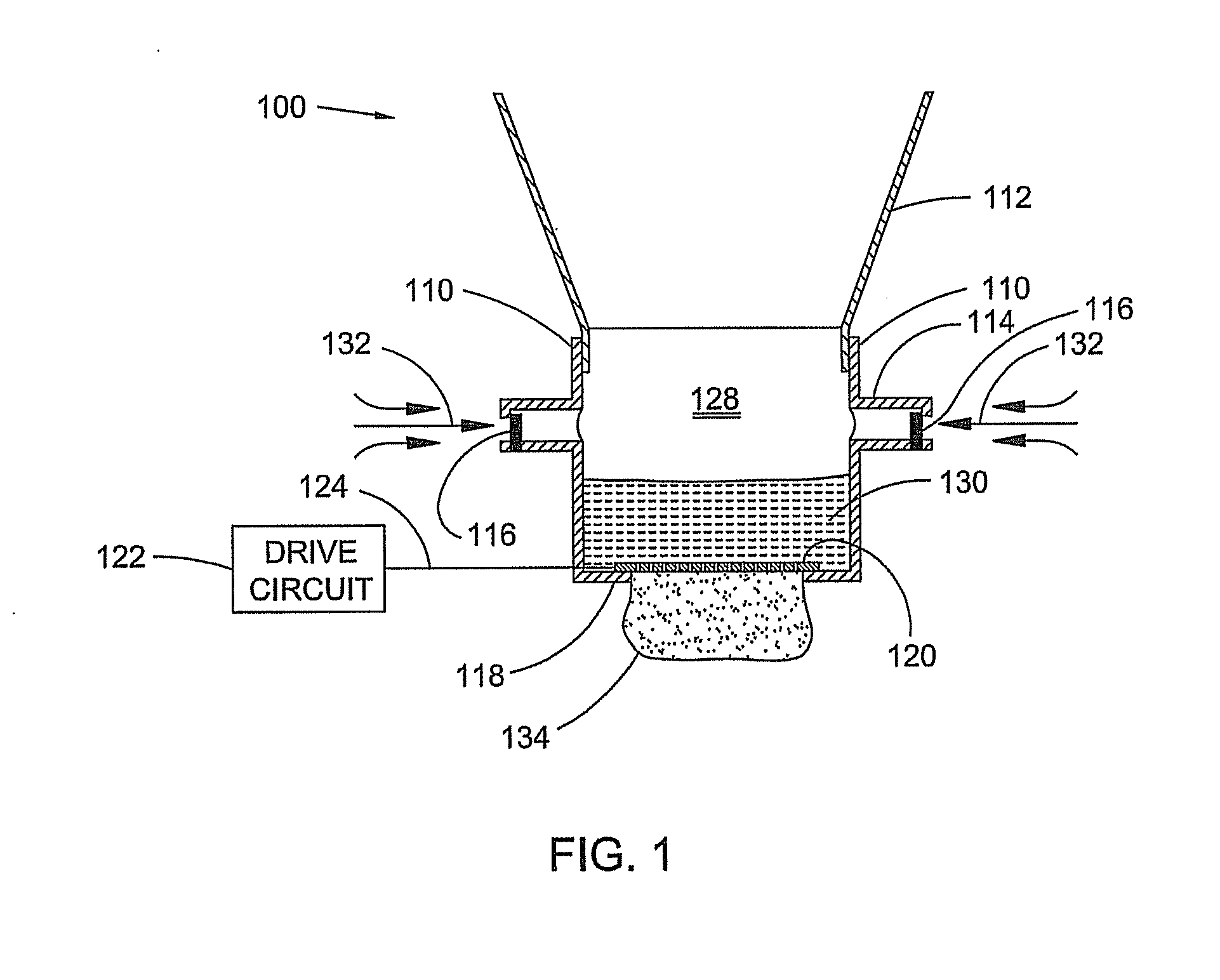
[0010]An exemplary embodiment of a piezoelectric foaming pump 100 is illustrated in FIG. 1. Pump 100 includes a body 110 which is connected to a liquid container 112. Liquid container 112 is used to contain a foamable liquid, such as, for example, soap, sanitizer, or moisturizer. Body 110 may be connected to liquid container 112 by any suitable means, such as, for example, a cap (not shown) secured to body 110 and screwed onto a threaded neck (not shown) of the liquid container 112, or welded or bonded by an adhesive to liquid container 112. Body 110 may include one or more air inlets 114. Air inlets 114 contain one-way valves 116, such as for example flapper valves. In addition, body 110 has a bottom surface 118 having an opening therein and is configured to receive a piezoelectric element 120, or atomizer. Piezoelectric element 120 includes a drive circuit 122. Drive circuit 122 provides electrical output signals along line 124 that cause piezoelectric element 120 to vibrate at a ...


PUM


Abstract

A piezoelectric foaming pump is provided herein. The piezoelectric foaming pump includes a housing having a first opening for receiving a liquid from a liquid container and a piezoelectric element secured to the housing. The piezoelectric element includes a plurality of holes there through. In addition, the housing includes an air inlet. Although the piezoelectric element has holes there through, prior to activating the piezoelectric element, liquid does not pass through the plurality of holes. When the piezoelectric element is energized, liquid passes through the plurality of holes due to the rapid vibration of the piezoelectric element and is dispensed as a foam. Additionally, a piezoelectric foaming pump having a fluid pump chamber; an air pump chamber; a mixing chamber; a piezoelectric element; and an outlet nozzle is disclosed herein. During operation, fluid pumped from the fluid chamber mixes with air pumped from an air chamber in the mixing chamber and the resulting mixture is passed through the piezoelectric element and dispensed out of a nozzle.

Description

CROSS REFERENCE TO RELATED APPLICATIONS[0001]The application claims the benefits of and priority to U.S. Provisional Patent Application entitled “Piezoelectric foaming pump,” Ser. No. 61 / 353,328 filed on Jun. 10, 2010, which is hereby incorporated by reference in its entirety.TECHNICAL FIELD[0002]The present invention generally relates to foaming pumps. Particularly, the present invention relates to a piezoelectric pump used to aerate a liquid, such as soap or sanitizer, to form a foam.BACKGROUND OF THE INVENTION[0003]Liquid dispensers, such as liquid soap and sanitizer dispensers, provide a user with a predetermined amount of liquid upon the actuation of the dispenser. Dispensed liquids may be difficult to spread resulting in less than desirable surface coverage on an individual's skin. For example, in the case of liquid sanitizer dispensers, the amount of sanitizer dispensed on an individual's hands is generally confined to a small area requiring the individual to physically sprea...

Claims


Application Information

Patent Timeline
Patent Type & Authority Applications(United States)
IPC IPC(8): B05B1/08
CPCB05B7/0037B05B7/005B05B11/0059F04B17/003B05B11/3087B05B17/0646F04B13/02B05B11/3016B05B11/1016B05B11/1087
Inventor WEGELIN, JACKSONPELFREY, KEITH ALLENSAYERS, RICHARD
Owner GOJO IND INC
Why Eureka
Try Eureka