Road barrier with warning function

A technology for isolating piers and roads, applied to roads, roads, road signs, etc., can solve the problems of drivers’ economic losses, car damage, and increased maintenance costs of traffic facilities, and achieve the effect of improving the sense of fineness and increasing alarm prompts

Inactive Publication Date: 2020-06-26
雷新刚
View PDF5 Cites 4 Cited by
  • Summary
  • Abstract
  • Description
  • Claims
  • Application Information

AI Technical Summary

Problems solved by technology

[0003] Because the height of the isolation pier is generally set very short, most of the isolation pier is in the blind area of ​​the driver. For some inexperienced drivers, the car will collide with the isolation pier due to the problem of sight when driving. Or rolling, on the one hand, it will cause damage to the car, which will cause economic losses to the driver; on the other hand, it will damage the isolation pier and increase the maintenance cost of traffic facilities

Method used


Image

  • Road barrier with warning function
  • Road barrier with warning function
  • Road barrier with warning function

Examples


Embodiment 1

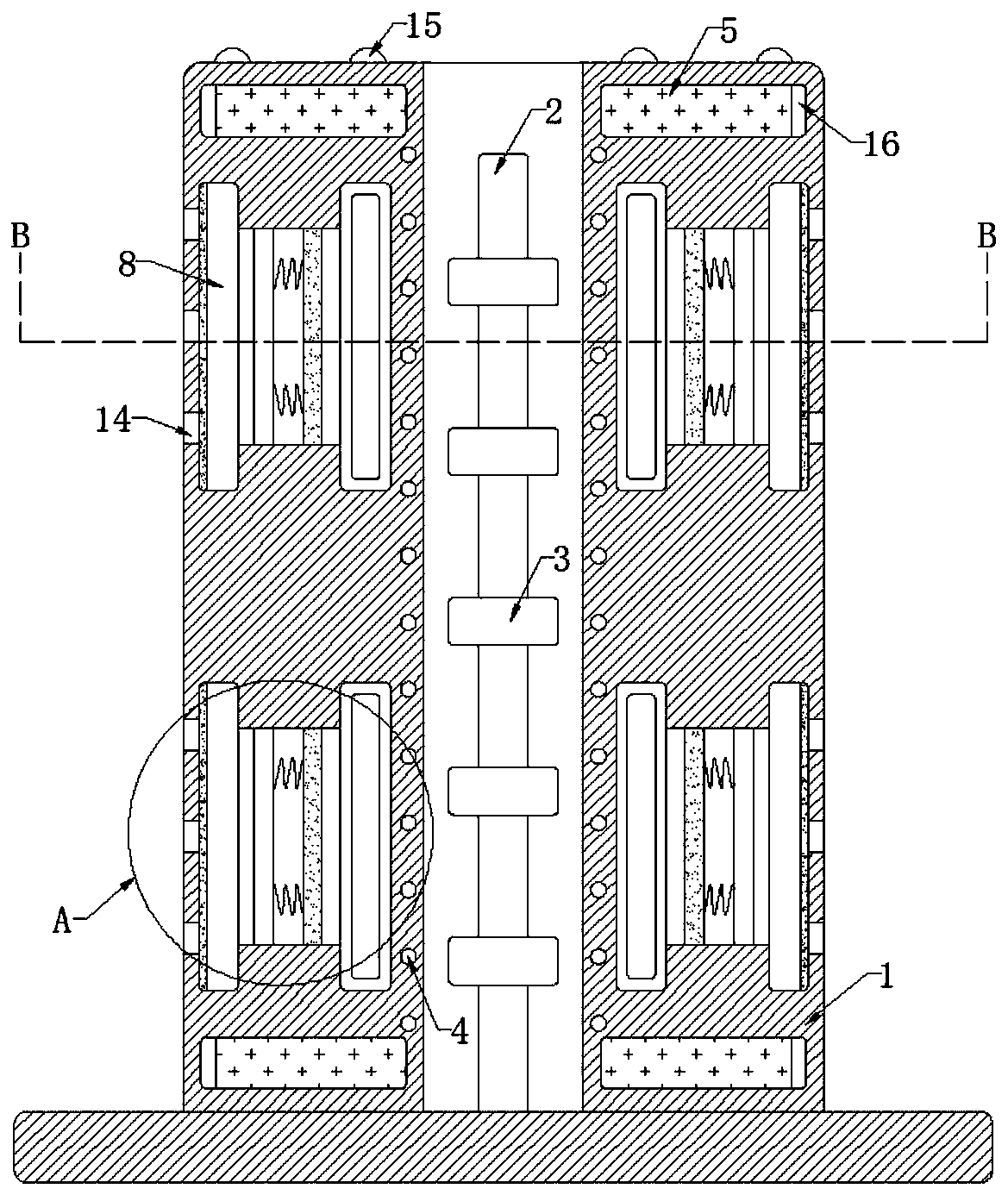
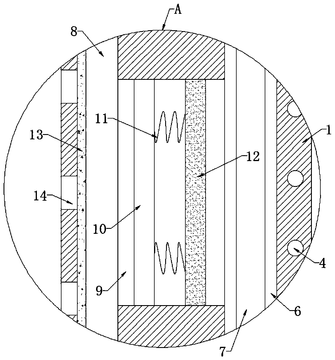
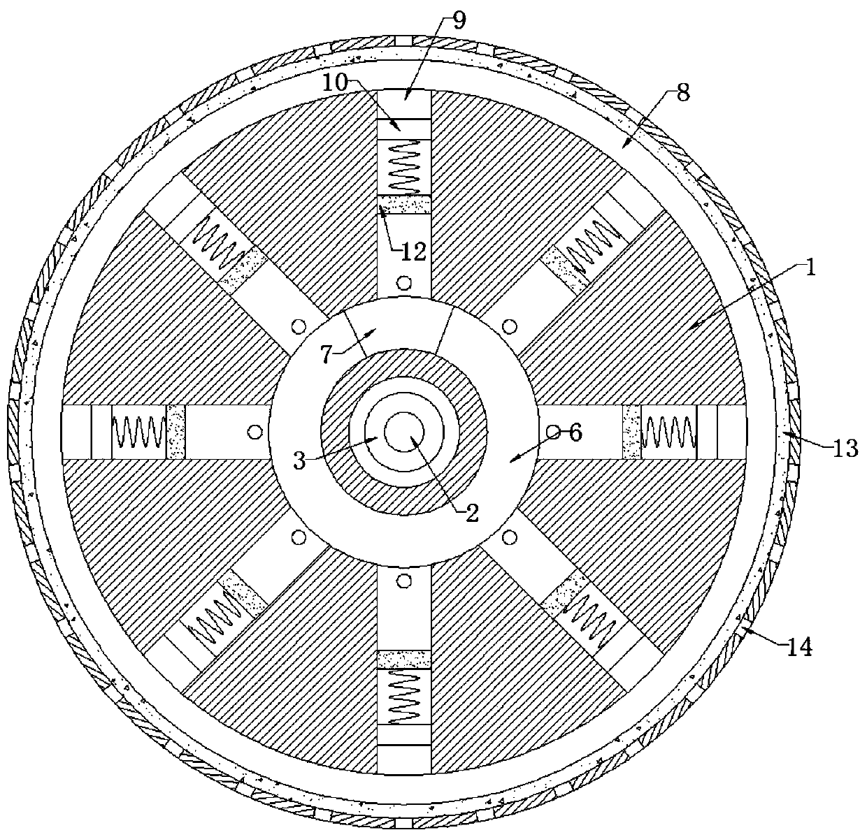
[0024] refer to Figure 1-3 , a road isolation pier with a warning function, comprising an annular pier body 1, the inner bottom of the annular pier body 1 is fixedly connected with a resonant rod 2, and the side wall of the resonant rod 2 is fixedly sleeved with a plurality of magnet blocks 3 with the same magnetic pole direction. The inner wall of the pier body 1 is embedded with an induction coil 4, and the car will vibrate during driving, thereby causing the resonant rod 2 to vibrate, so that the resonant rod 2 drives the magnet block 3 to vibrate. At this time, the induction coil 4 reciprocates relative to the magnet block 3, And cutting the magnetic induction line, so that the induction coil 4 generates an induced current, the inner wall of the annular pier body 1 is provided with an annular cavity 6, the inner wall of the annular cavity 6 is slidingly connected with a conductive block 7 coupled with the induction coil 4, and the side wall of the annular pier body 1 is pr...

Embodiment 2

[0030] refer to Figure 4 , different from Embodiment 1, the permanent magnet block 12 is in damping contact with the inner wall of the cavity 9, and the damping coefficient between each cavity 9 and the corresponding permanent magnet block 12 is different, and the diameter of each cavity 9 is different. same.

[0031]In this embodiment, since the diameters of the cavities 9 are not the same, and the damping coefficients between the cavities 9 and the permanent magnet blocks 12 are not the same simultaneously, when the conductive block 7 passes over the cavity, each permanent magnet block 12 different motion states, thereby ensuring that the vibrating cavity 8 can produce more complex and detailed vibration changes, thereby prompting the diaphragm 13 to produce more delicate and diverse changes, which is convenient for the driver to monitor the warning sound generated on the ring pier 1. Distinguish, avoid vehicle body and annular pier body 1 to collide, also can make the ran...


PUM


Abstract

The invention discloses a road barrier with a warning function. The pier comprises an annular pier body, the inner bottom of the annular pier body is fixedly connected with a resonance rod; the side wall of the resonance rod is fixedly sleeved with a plurality of magnet blocks with the same magnetic pole direction, an induction coil is embedded in the inner wall of the annular pier body, an annular cavity is formed in the inner wall of the annular pier body, the inner wall of the annular cavity is slidably connected with a conductive block in coupled connection with the induction coil, and anannular vibration cavity is formed in the side wall of the annular pier body. According to the invention, the resonance rod is driven to vibrate through vibration generated in the driving process of an automobile; the induction coil moves relative to the magnet block and cuts the dynamic induction line; the induction coil generates induction current and electrifies the conductive block, so that the conductive block moves along the inner wall of the annular cavity and continuously sweeps the cavity, the permanent magnet block and the conductive block continuously generate magnetic attraction force, quick vibration of the vibrating diaphragm is promoted, sound is emitted outwards through the generation hole, and an alarm prompt is given to a driver.

Description

technical field [0001] The invention relates to the technical field of traffic facilities, in particular to a road isolation pier with a warning function. Background technique [0002] The road isolation pier is a basic traffic facility, mainly used to limit the driving and parking areas of road vehicles. [0003] Because the height of the isolation pier is generally set very short, most of the isolation pier is in the blind area of ​​the driver. For some inexperienced drivers, the car will collide with the isolation pier due to the problem of sight when driving. Or rolling, on the one hand, it will cause damage to the car, thereby causing economic losses to the driver, and on the other hand, the isolation pier will be damaged, increasing the maintenance cost of the traffic facilities. [0004] Therefore, we propose a road separation pier with warning function to solve the above problems. Contents of the invention [0005] The purpose of the present invention is to solve...

Claims


Application Information

Patent Timeline
Patent Type & Authority Applications(China)
IPC IPC(8): E01F13/00E01F9/608E01F9/615
CPCE01F13/00E01F9/608E01F9/615
Inventor 雷新刚
Owner 雷新刚
Why Eureka
Try Eureka