

Surge absorbing element
a technology surge absorbing element, which is applied in the direction of overvoltage protection resistor, emergency protective arrangement for limiting excess voltage/current, and arrangement responsive to excess voltage, etc., can solve the problem of surge absorbing element resistance further declining, surge absorbing element resistance against static electricity is difficult to lower, and the quality of high-speed signals is deteriorated
- Summary
- Abstract
- Description
- Claims
- Application Information
AI Technical Summary
Benefits of technology
Problems solved by technology
Method used
Image

Examples
examples
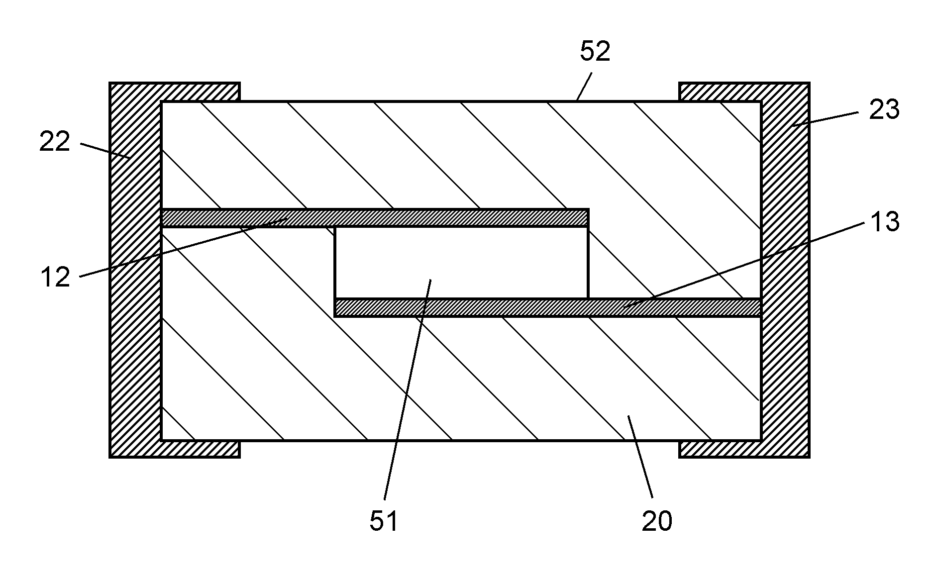
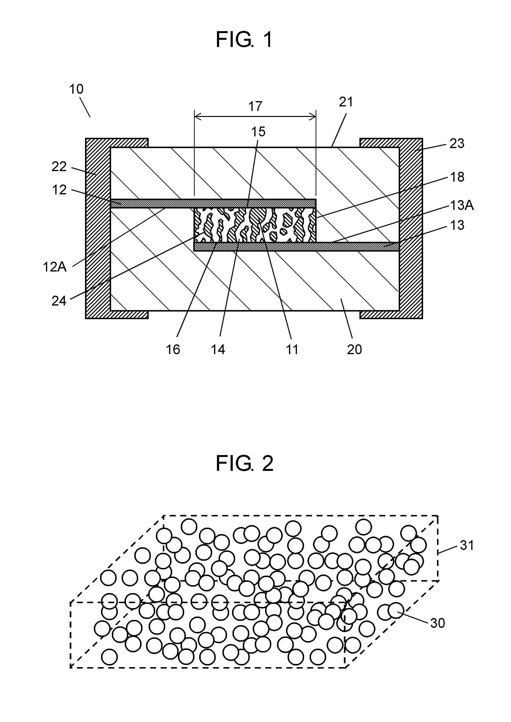
[0063]Hereinafter, the advantageous effects of the present embodiment will be described by way of specific examples of surge absorbing element 10 illustrated in FIG. 1.
examples 1 to 7
[0064]First, an oxide powder of ZnO as a main component, and oxide powders of SrCoO3 and Co2O3 as secondary components are prepared as starting materials of ceramic layer 11. The starting materials are weighed to cause ceramic layer 11 to have a composition ratio of (ZnO)0.97(SrCoO3)0.03.
[0065]These starting material powders are put into a ball mill made of polyethylene, and then stone balls made of stabilized zirconia, and pure water are added thereto. The components therein are mixed with each other for about 20 hours, and then the mixture is dehydrated and dried to prepare a dry powder. Next, this dry powder is put into a crucible made of high-purity alumina, and calcined at about 750° C. for 2 hours to prepare a calcined powder. Furthermore, this calcined powder, stone balls made of stabilized zirconia, and pure water are put into a ball mill made of polyethylene to pulverize the powder for about 20 hours. The pulverized powder is then dehydrated and dried to prepare a ceramic p...
examples 8 to 10
[0075]In each of Examples 8 to 10, a ceramic paste is used, in which the ceramic powder, the organic binder, the plasticizer and the solvent in Example 1 are mixed without incorporating the resin particles into the ceramic paste in Example 1, and the content by percentage of the organic binder is variously changed. In the same way as in Example 1 except this matter, surge absorbing elements 10 are produced.
PUM
 Abstract
Description
Claims
Application Information