Centrifugal liquid separation machine using pressurized air to promote solids transport

a centrifugal liquid separation and pressurized air technology, applied in centrifuges, rotary centrifuges, etc., can solve the problems of increasing the size of bubbles, and achieve the effects of reducing the damage to the machine and specifically at the discharge opening, increasing the reliability of the air delivery system, and preventing short circuiting of the heavy phase discharge path

Active Publication Date: 2011-12-15
CENTRISYS CORP
View PDF13 Cites 7 Cited by
  • Summary
  • Abstract
  • Description
  • Claims
  • Application Information

AI Technical Summary

Benefits of technology

[0034]According to another advantage of the present invention, the air delivery system enters the machine through the back drive system. This increases the reliability of the air delivery system and allows for the addition of other value added components without interference from the air delivery system of the present invention.
[0035]According to further advantage of the present invention, short circuiting of the heavy phase discharge path is prevented. This is accomplished in the present invention by uniformly injecting air into the heavy phase material within the heavy phase material exit path.
[0036]According to a still further advantage of the present invention, a continuous process control is provided in real time. The continuous process control operates by measuring the properties of the heavy phase discharge stream with a sensor, and adjusting the continuous air supplied accordingly to vary to discharge rate of the heavy phase liquid in order to achieve a desired heavy phase liquid discharge consistency.
[0037]According to a still further advantage yet of the present invention, grit and other fine particles are expelled from a screw type centrifugal machine without using a beach. This is accomplished by the present invention by using turbulence inducers to at least partially re-suspend the grit within the heavy phase material discharge flow path.
[0038]According to a still further advantage yet of the present invention, abrasive damage to the machine and specifically at the discharge openings is reduced. This is accomplished in the present invention by eliminating the need for very small discharge openings and by discharging at a reduced bowl diameter.

Problems solved by technology

First, as an air bubble is a compressible gas, the bubble will increase in size as the air particle gets closer to the pool surface.

Method used


Image

  • Centrifugal liquid separation machine using pressurized air to promote solids transport
  • Centrifugal liquid separation machine using pressurized air to promote solids transport
  • Centrifugal liquid separation machine using pressurized air to promote solids transport

Examples


Embodiment Construction

[0046]While the invention will be described in connection with one or more preferred embodiments, it will be understood that it is not intended to limit the invention to those embodiments. On the contrary, it is intended to cover all alternatives, modifications and equivalents as may be included within the spirit and scope of the invention as defined by the appended claims.

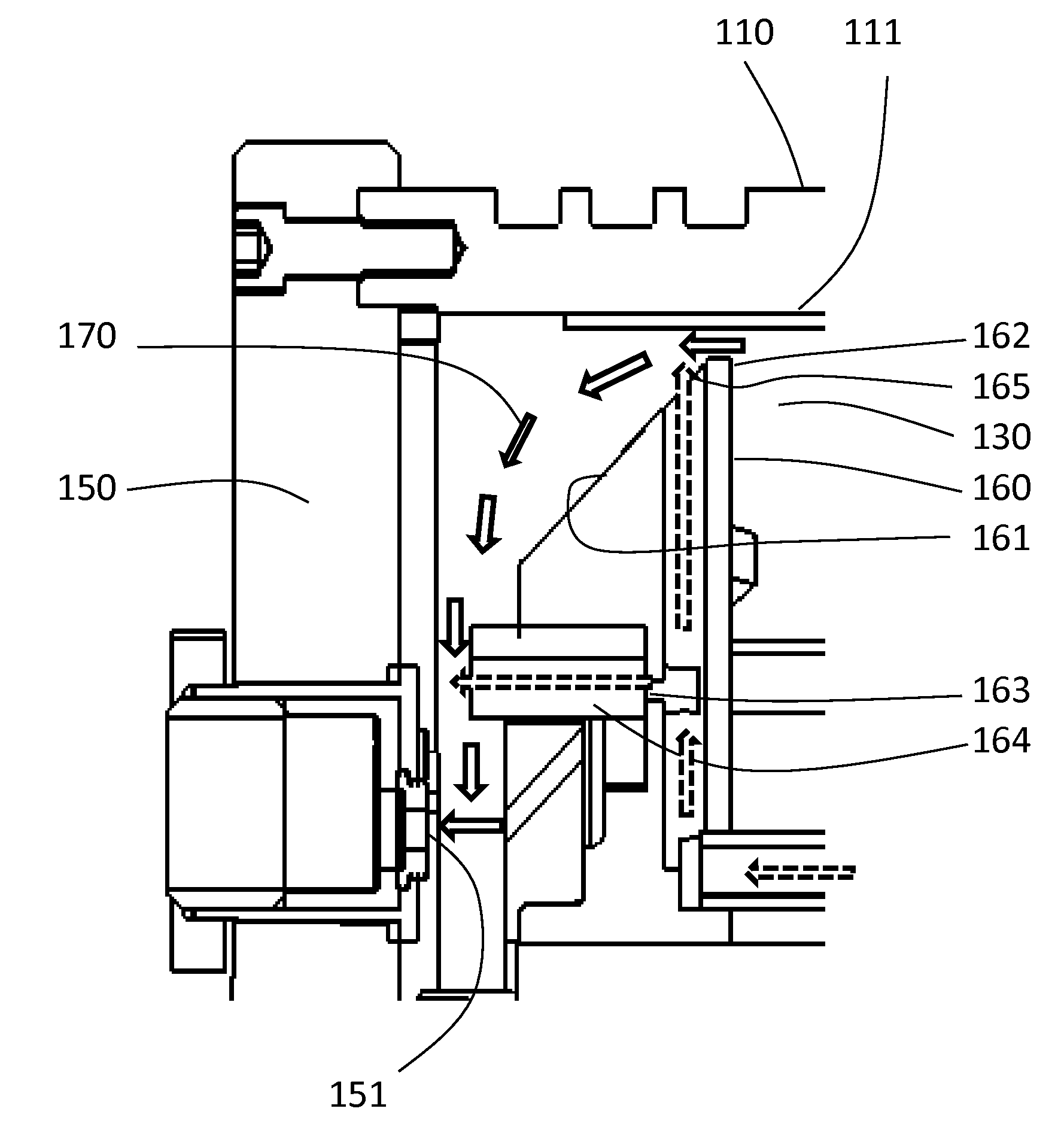
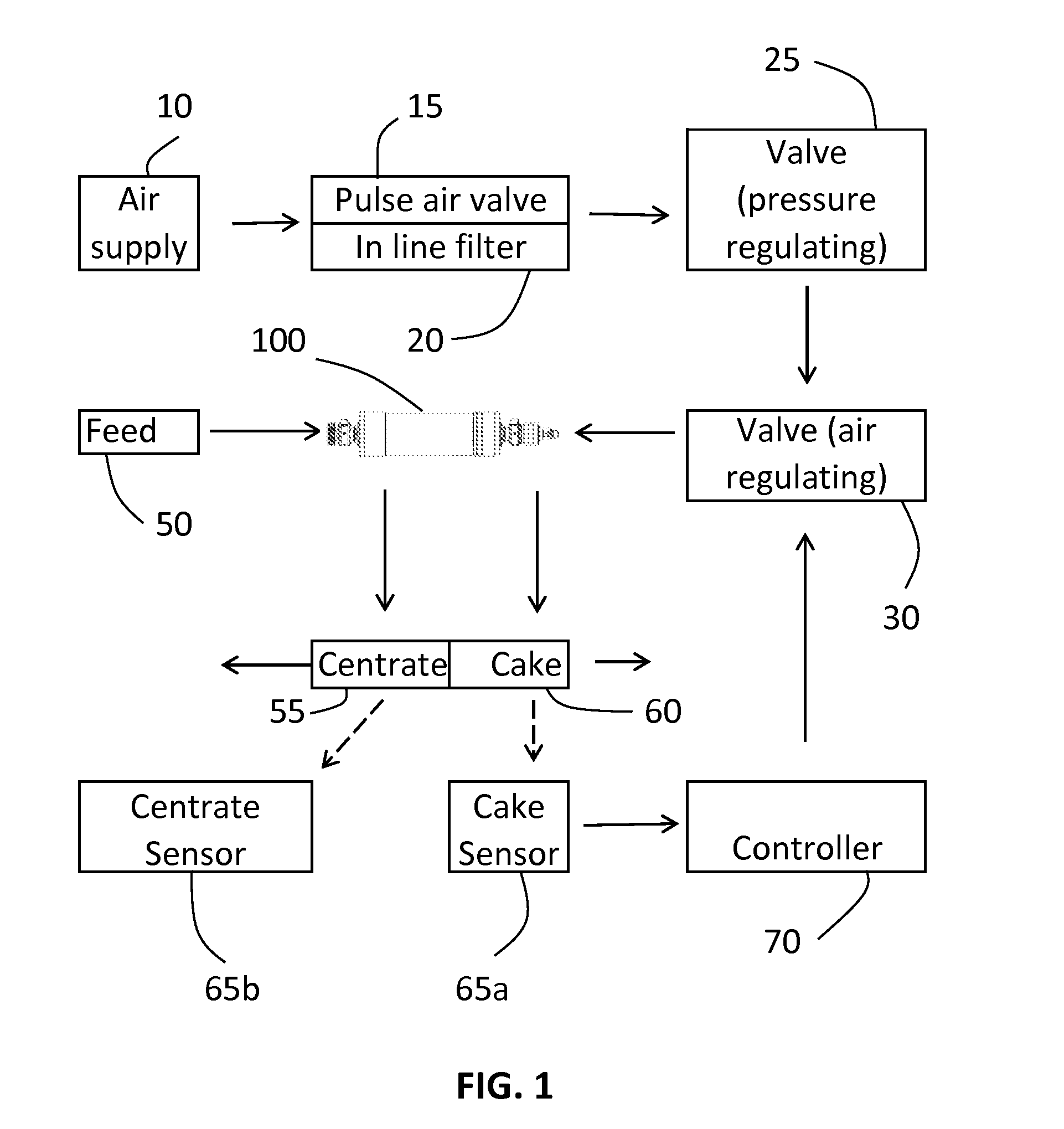
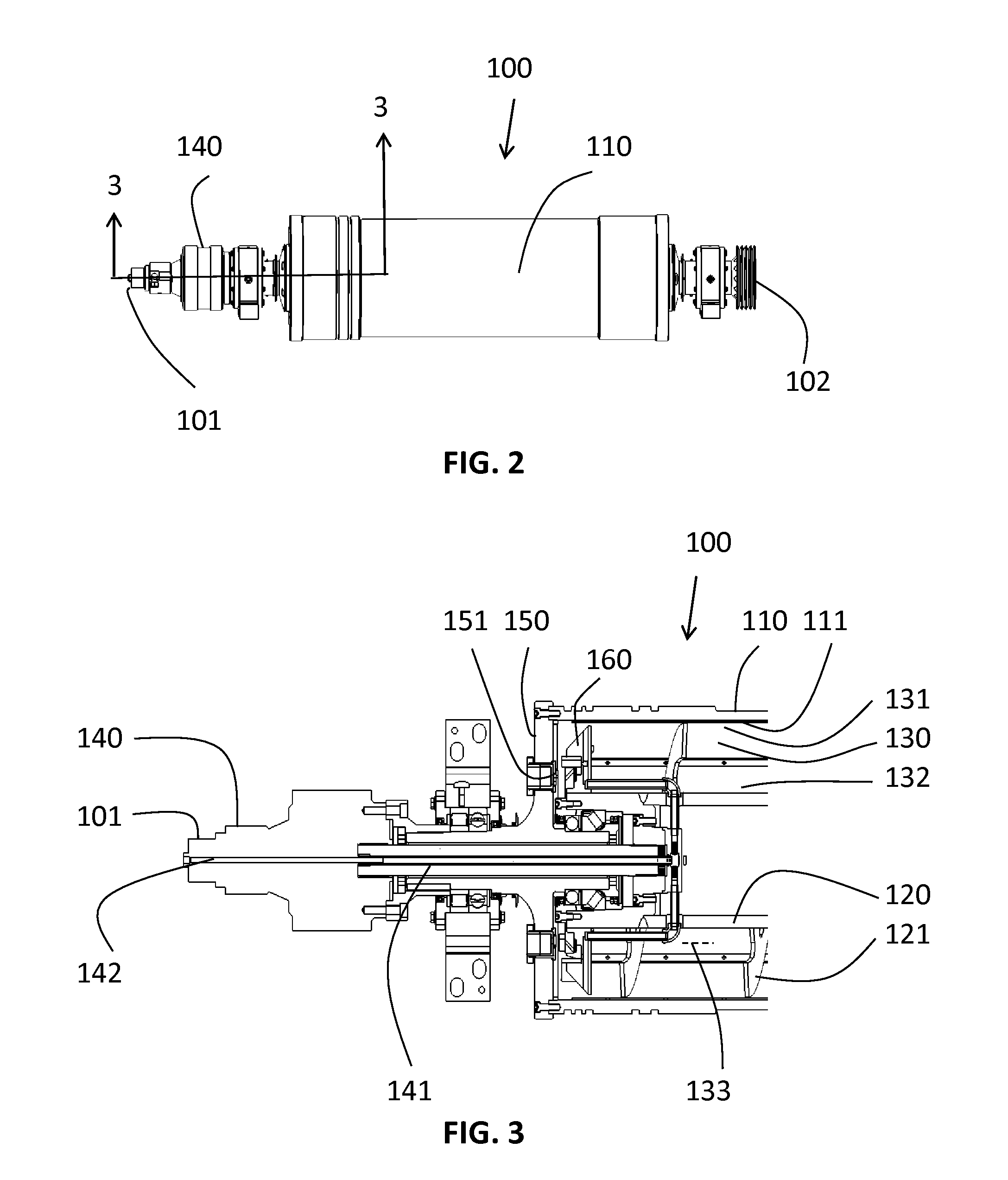
[0047]Looking now at FIG. 1, it is seen schematically that several components interact with the machine 100, the operation of which achieves at least one of the advantages of the present invention. Compressed air can be supplied from an air supply 10. A pulse air valve 15 and filter 20 can be provided. A pressure regulator 25 and an air regulator 30 are further provided. Components 10, 15, 20, 25 and 30 form an external air delivery system. The pressure regulator 25 can regulate pressure between 5 and 500 psi, and preferably operates between 30 and 100 psi. The air regulator can supply between 1 and 50 SCFM, and p...


PUM


Abstract

A screw type centrifugal liquid separation machine having a continuous decanter and using pressurized air to promote solids transport is provided. The machine has an outer bowl and a conveyor, which are coaxial. A back drive assembly is provided to maintain a difference in speed between the bowl and conveyor so that the conveyor has a mechanical sweeping action within a separation region of the machine. Air is introduced into the machine through the back drive assembly, and is injected into the heavy phase discharge path. In one location, the air acts as a turbulence inducer that at least partially re-suspends grits within the heavy phase material. The air is also injected through lift injectors radially spaced about the solids baffle to provide a uniform solid phase driving force. A flow control is also provided for controlling the discharge rate of the heavy phase material through a discharge port.

Description

[0001]This United States utility patent application claims priority on and the benefit of provisional application 61 / 355,023 filed Jun. 15, 2010, the entire contents of which are hereby incorporated herein by reference.BACKGROUND OF THE INVENTION[0002]1. Field of the Invention[0003]The present invention relates to a centrifugal liquid separation machine, and in particular to a screw type centrifugal liquid separation machine having a continuous decanter and using pressurized air to promote solids transport.[0004]2. Description of the Related Art[0005]Centrifugal machines are useful in many types of applications. In one application, wastewater treatment plants, it is desired to achieve a 4% to 6% cake solids discharge. This range of cake solids is required in order for an anaerobic digester to operate efficiently. Falling below this range requires increased digester capacity. Rising above this range typically results in mixing problems due to the thickness of the heavy phase liquids....

Claims


Application Information

Patent Timeline
Patent Type & Authority Applications(United States)
IPC IPC(8): B04B1/20B04B11/02
CPCB04B1/20B04B11/02B04B2001/2091B04B2001/2041
Inventor KOPPER, MICHAELHAVRIN, ROBERT
Owner CENTRISYS CORP
Why Eureka
Try Eureka