
Device for performing end-to-end anastomosis

a technology of end-to-end anastomosis and device, which is applied in the field of end-to-end anastomosis devices and processes, can solve the problems of long anastomosis time, difficult to learn and perform laparoscopic anastomosis, and negative effect on patients,

Inactive Publication Date: 2011-12-15
HOSPITAL FOR SICK CHILDREN
View PDF2 Cites 9 Cited by
  • Summary
  • Abstract
  • Description
  • Claims
  • Application Information

AI Technical Summary

Benefits of technology

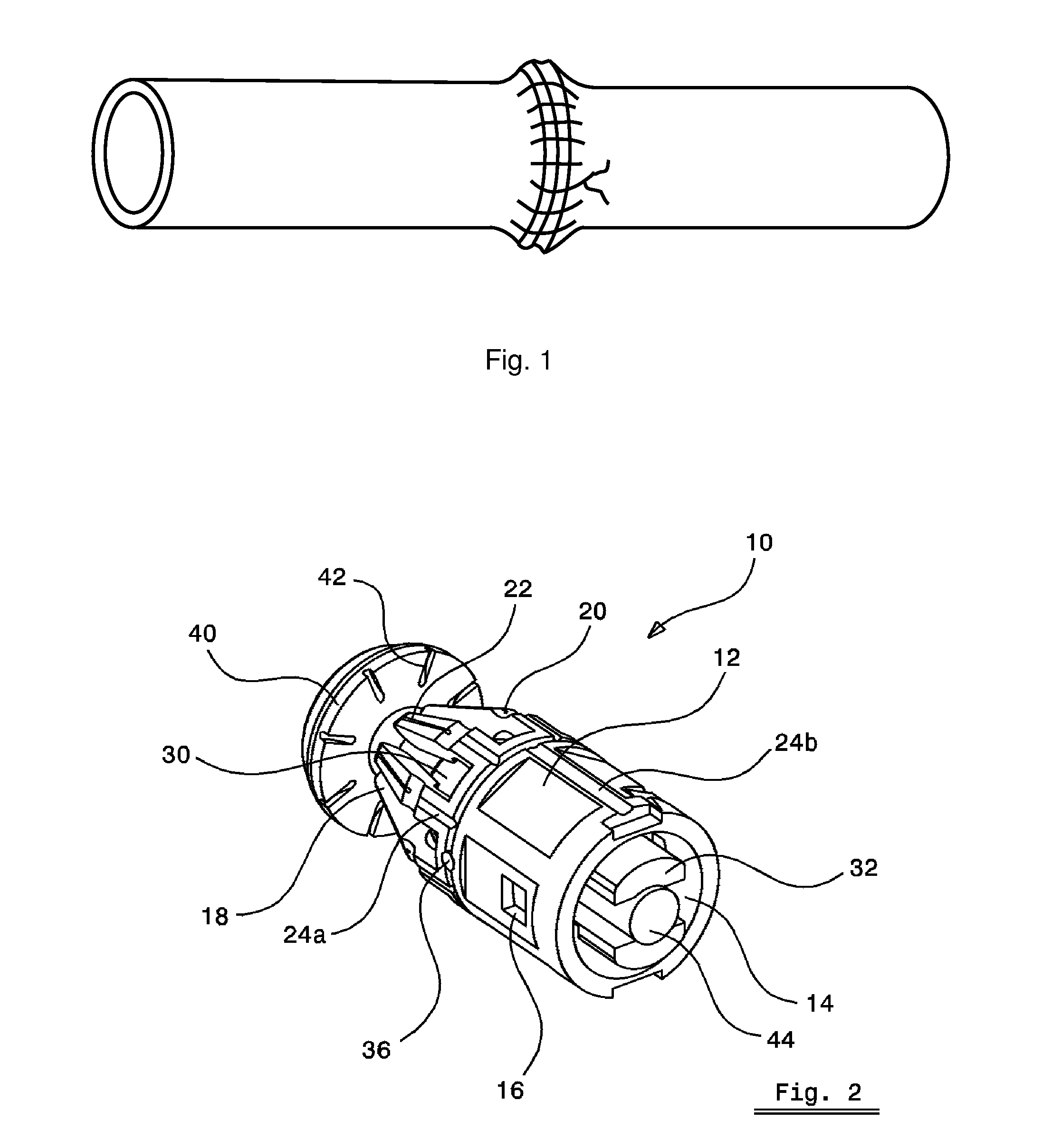
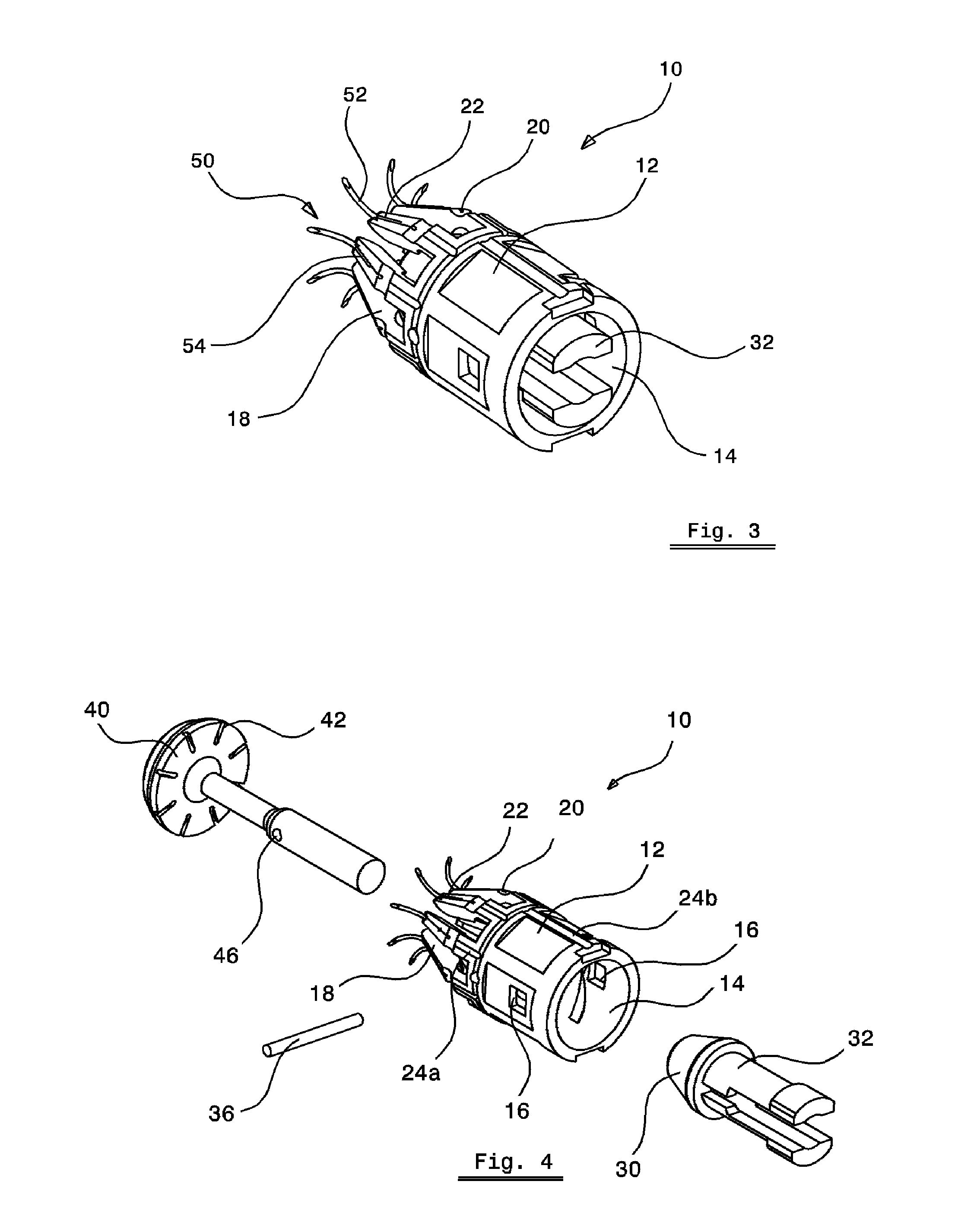
The present invention provides an anastomosis device for joining anatomical tubular structures during surgery. The device includes a support housing with a compliant flexible section and a plurality of suture needles mounted on the outer surface of the compliant flexible section. An introducer with a circular disc section is attached to the support housing and an deformation mechanism is activated to force the plurality of suture needles to pierce through the wall of the anatomical tubular structure simultaneously. The device can be used with a laparoscopic deployment tool for minimally invasive surgery. The technical effect of the invention is to provide a device that simplifies the anastomosis process and reduces the risk of complications.

Problems solved by technology

However, in minimally invasive surgery (MIS) where the procedure is performed through small incisions in the patient's skin, anastomosis is an extremely difficult skill to learn and execute.
Needless to say, the long anastomosis time has a negative impact on the patient due to increased anesthesia requirement.
For the surgeon, laparoscopic anastomosis is extremely difficult to learn and perform, and is very fatiguing in nature.
Increased anastomosis time is also a burden on the healthcare provider as it takes up valuable operating room time and adds to the personnel cost.
Even though the two ends of the design are attached through a flexible coupler, the design lacks a good suture management scheme and will suffer from suture tangling.

Method used


Image

  • Device for performing end-to-end anastomosis
  • Device for performing end-to-end anastomosis
  • Device for performing end-to-end anastomosis

Examples


Embodiment Construction

[0034]Without limitation, the majority of the systems described herein are directed to an anastomosis device and method of using the same. As required, embodiments of the present invention are disclosed herein. However, the disclosed embodiments are merely exemplary, and it should be understood that the invention may be embodied in many various and alternative forms.

[0035]The Figures are not to scale and some features may be exaggerated or minimized to show details of particular elements while related elements may have been eliminated to prevent obscuring novel aspects. Therefore, specific structural and functional details disclosed herein are not to be interpreted as limiting but merely as a basis for the claims and as a representative basis for teaching one skilled in the art to variously employ the present invention. For purposes of teaching and not limitation, the illustrated embodiments are directed to an anastomosis device and method of using the same.

[0036]As used herein, the...


PUM


Abstract

Herein is provided an anastomosis device which includes a cylindrical support housing having a tapered section being formed of a plurality of compliant fingers integrally formed around the circumference of an end of the cylindrical section which can flex at their connection point to the cylindrical section. Each compliant finger holds a suture needle. The device includes a push rod having a cam head at one end of the rod section. The cam head is located adjacent to the tapered portion. In operation the anastomosis device is aligned with the anatomical tubular structure undergoing an anastomosis process. When a back end of the push rod is pushed towards the tapered section of the support housing, the cam head section bears against an inner surface causing each compliant finger to flex radially outwards forcing the suture needles to simultaneously pierce the wall of the anatomical tubular structure.

Description

CROSS REFERENCE TO RELATED U.S. PATENT APPLICATION[0001]This patent application relates to U.S. provisional patent application Ser. No. 61 / 353,974 filed on Jun. 11, 2010, entitled DEVICE FOR PERFORMING END-TO-END ANASTOMOSIS, filed in English, which is incorporated herein in its entirety by reference.FIELD OF THE INVENTION[0002]The present disclosure relates to a device for accomplishing the surgical process of anastomosis i.e. connecting two structures (commonly tubular structures) to restore continuity after resection or to bypass an unresectable disease process. More particularly the present disclosure relates to a device and process for connecting the structures in an end-to-end fashion.BACKGROUND OF THE INVENTION[0003]A common requirement in many surgical procedures is the resection or bypass of a diseased organ. Often the diseased section is a part of a tubular structure (e.g. artery, bowel, esophagus) and after the resection it is required to reattach the resulting two health...

Claims


Application Information

Patent Timeline
Patent Type & Authority Applications(United States)
IPC IPC(8): A61B17/11
CPCA61B17/0469A61B17/1114A61B2017/047A61B2017/1132A61B2017/0608A61B2017/1107A61B2017/0472
Inventor BASSAN, HARMANPREETKIM, PETERLOOI, THOMAS
Owner HOSPITAL FOR SICK CHILDREN
Learn More