Measuring of a landing platform of a ship

Inactive Publication Date: 2011-12-15
UMS SKELDAR SWEDEN AB
View PDF6 Cites 58 Cited by
  • Summary
  • Abstract
  • Description
  • Claims
  • Application Information

AI Technical Summary

Benefits of technology

[0007]It is therefore an objective of the present invention to provide a system and a method, that are less vulnerable to disruptions and

Problems solved by technology

In particular, when trying to land on a platform of a ship, the landing process is more difficult since the sea continuously changes the attitude of the ship and the landing platform.
Also the fact that the ship is moving in a specific bearing further complicates the landing on the platform.
For example, if there is a heavy sea, the amplitude of the waves can chan

Method used


Image

  • Measuring of a landing platform of a ship
  • Measuring of a landing platform of a ship
  • Measuring of a landing platform of a ship

Examples


Embodiment Construction

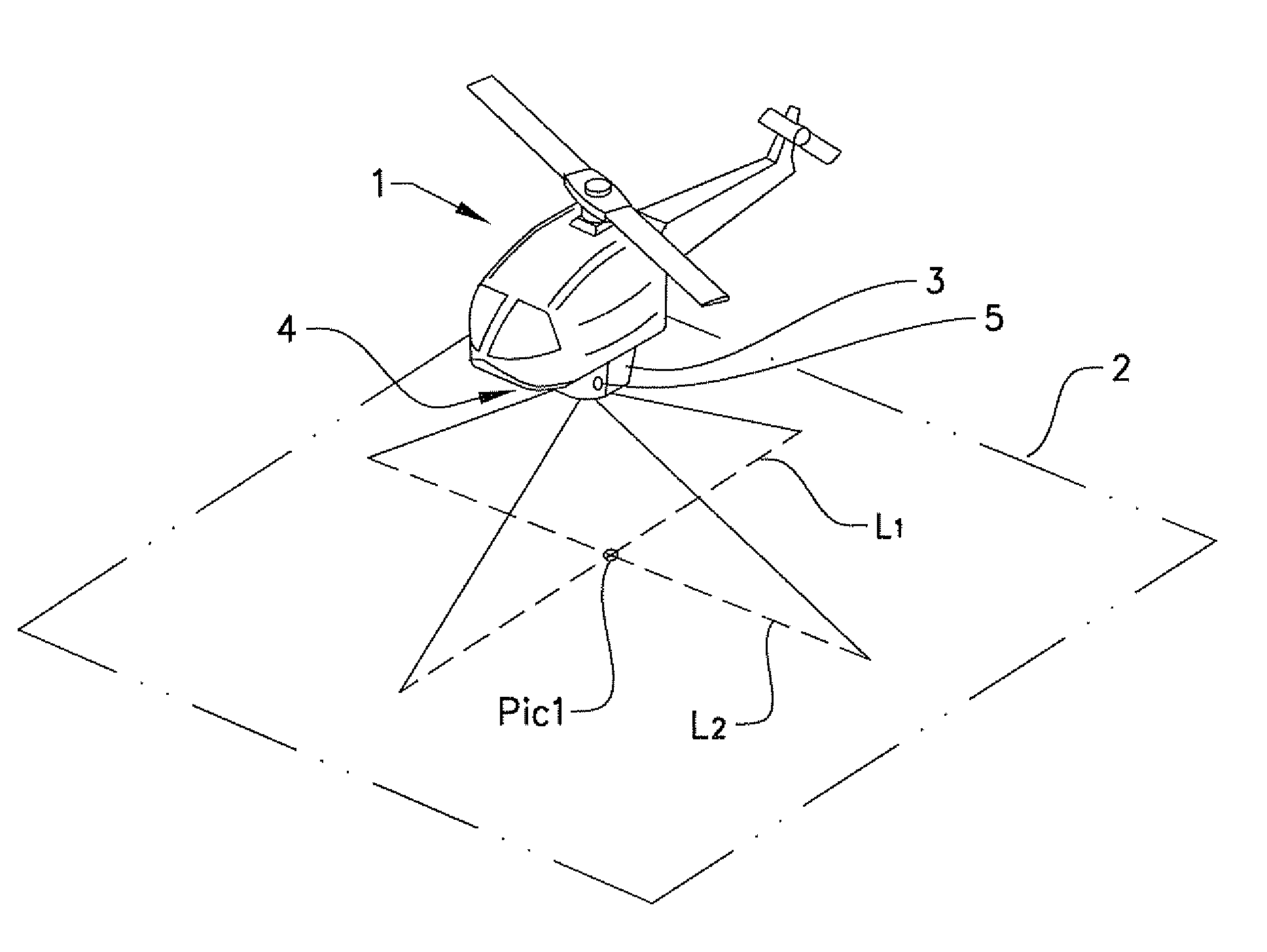
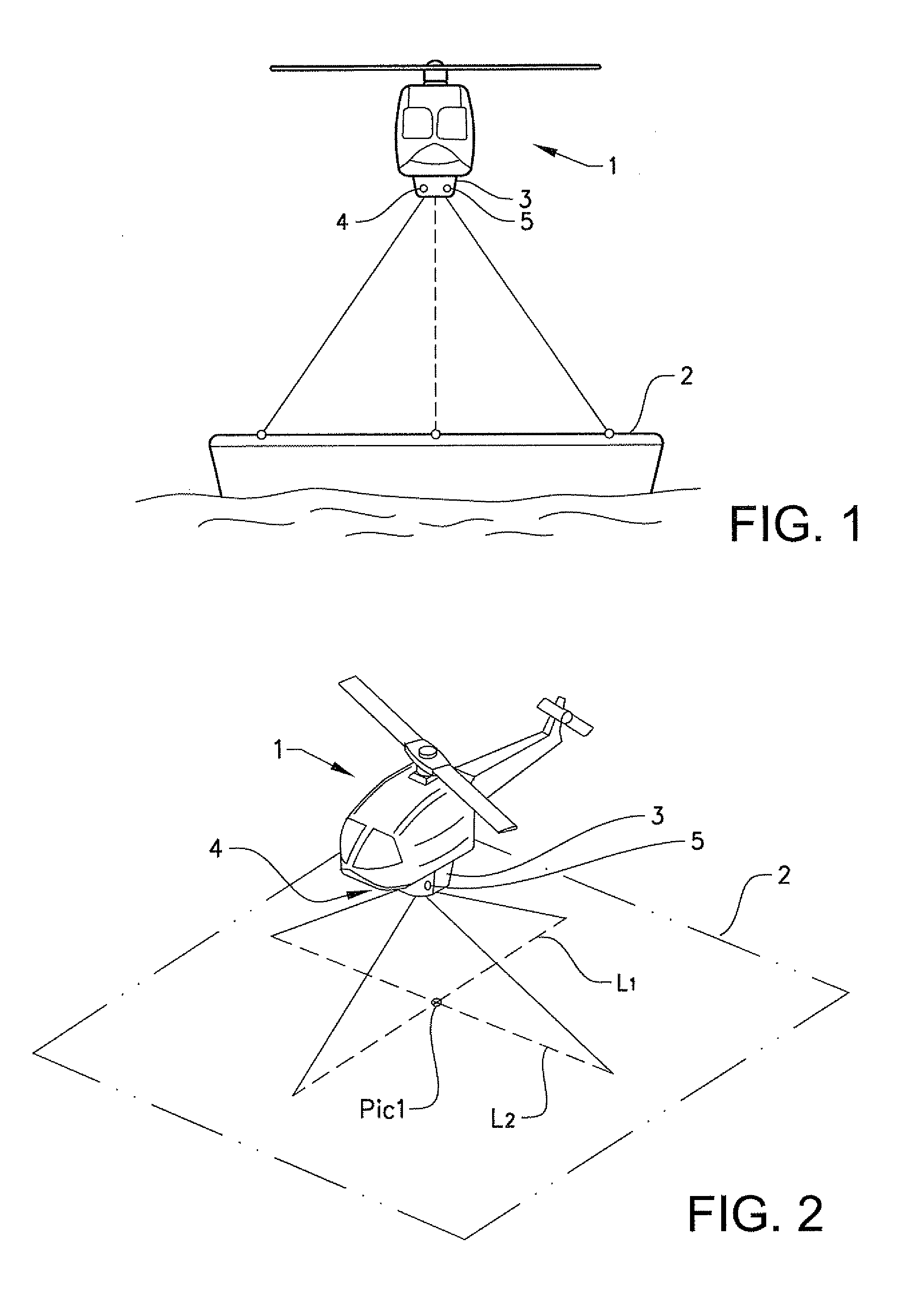
[0022]FIG. 1 shows an unmanned aerial vehicle (UAV) 1, in the present case a helicopter, which has moved into a position above a surface 2 of the landing platform of a ship at sea. The UAV is equipped with a system 3 for autonomous landing which comprises at least two moveable laser distance meters 4, 5.

[0023]In FIG. 2 it is illustrated how the measuring of the landing platform is performed according to an embodiment of the invention. The laser distance meters 4, 5 of the system 3 emit beams in rapid successive order in predetermined angle steps in such a way that spots are projected along at least one straight line (L1, L2) on the surface 2 of the platform by each of the laser distance meters. The movements of the laser distance meters are performed in a perpendicular direction to each other and consequently the at least two straight lines are crossed so that they have at least one point of intersection in common Pic1. This point thereby constitutes a control value since the same v...


PUM


Abstract

A system for predicting the movement of a surface for autonomous landing of unmanned aerial vehicles thereon. At least two beam emitters are each movable to measure along at least one line on the surface. The lines measured by the two beam emitters are crossed so that they have at least one point of intersection in common. A control module. A detector is configured to detect reflected beams. A processor is configured to process measurements including estimating continuously a plane to the surface by measurements during a time interval. A storage module is configured to store the processed measurements.

Description

TECHNICAL FIELD[0001]The present invention relates to a system and a method for autonomous landing of unmanned aerial vehicles on a surface.BACKGROUND OF THE INVENTION[0002]When landing an unmanned aerial vehicle (UAV), such as an unmanned helicopter, it is important that the aerial vehicle has access to accurate information regarding movement, position and attitude relative to the ground or landing area. In particular, when trying to land on a platform of a ship, the landing process is more difficult since the sea continuously changes the attitude of the ship and the landing platform. Also the fact that the ship is moving in a specific bearing further complicates the landing on the platform. The inclination of the platform is determined by the pitch and the roll, and there is also a movement in the vertical direction. For example, if there is a heavy sea, the amplitude of the waves can change the distance between the ship and the UAV by quite a large amount. It is important that an...

Claims


Application Information

Patent Timeline
IPC IPC(8): G05D1/10G01S17/933
CPCG05D1/0684G01S17/933
Inventor HOGSTROM, TOMAS
Owner UMS SKELDAR SWEDEN AB
Why Eureka
Try Eureka