Method and device for measuring deposit thickness

a technology of deposit thickness and measurement method, which is applied in the direction of material thermal analysis, cleaning process and apparatus, instruments, etc., can solve the problems of reducing the cross-sectional area of the pipeline, affecting the accuracy of the measurement method, so as to improve the wax thickness measurement method

Inactive Publication Date: 2011-12-22
DEN NORSKE STATS OLJESELSKAP AS
View PDF4 Cites 24 Cited by
  • Summary
  • Abstract
  • Description
  • Claims
  • Application Information

AI Technical Summary

Benefits of technology

[0018]It is an object of the present invention to at least partly overcome the above problems, and to provide an improved wax thickness measurement method. This object, and other objects that will be apparent from the following description, is achieved by a method and device according to the appended independent claims. Advantageous embodiments are set forth in the appended dependent claims.

Problems solved by technology

Wax deposition at the inside wall of oil pipelines is a severe problem in today's oil production infrastructure.
This in turn will reduce the pipeline cross-sectional area, which without proper counter measures will lead to a loss of pressure and ultimately to a complete blockage of the pipeline.
Pigging is a complex and expensive operation.
If more wax is deposited than the pig diameter is designed for the pig might get stuck in the pipeline, resulting in costly operations and stop in production to remove the pig.
Chemical inhibition is also expensive and there are currently no chemicals available that completely reduce wax deposition.
The results of such inhibition are uncertain and the intervals and amounts of chemicals used are therefore often unnecessarily high.
Further, the chemicals that are used are classified as environmentally very problematic and the dosage of such chemicals should be kept to a minimum.
Electric heating above the wax appearance temperature is very expensive due to both high installation and operational costs.
Accordingly, electric heating is not feasible for long-distance transport.
This results in increased costs and risks in production as well as a negative impact on the environment.
In addition, the profile or shape of the pipeline or any process equipment may have an impact on the rate of deposit build-up, which is not possible to simulate correctly in a laboratory.
However, each of these known techniques has several drawbacks.
For instance, pigs and pressure pulse techniques give no continuous measurement, and they may disturb operation procedures, as well as being expensive.
The method described in U.S. Pat. No. 6,886,393 has no means of calibrating accordingly, taking these is parameters into account when a deposit layer is present, and will therefore not provide the necessary accuracy in thickness calculation.

Method used


Image

  • Method and device for measuring deposit thickness
  • Method and device for measuring deposit thickness
  • Method and device for measuring deposit thickness

Examples


example 1

[0080]The following example shows a method for conducting a measurement with various deposit thicknesses, with reference to FIG. 3 and FIG. 4:

[0081]After a cleaning cycle at the first unit 20, comprising activation of the first heating element 22, heating the inside wall 2 of a pipeline above the wax appearance temperature, and cooling of the pipe wall 1 in the first section to the same temperature as that of the second section, the heat elements 22 and 23 are switched on from t=10 s to t=40 s with a constant electric power of 400 W.

[0082]This heating generates a linear rise of the measured temperature at the position of the heat sensors as seen in FIG. 3. When the heat elements are switched off, the generated heat will dissipate. Due to the insulating effect of the deposit this will take longer with growing deposit thickness. A certain measurement time t(measurement) is defined, preferably at a time where the spread between the temperature curves for minimum and maximum deposit thi...

example 2

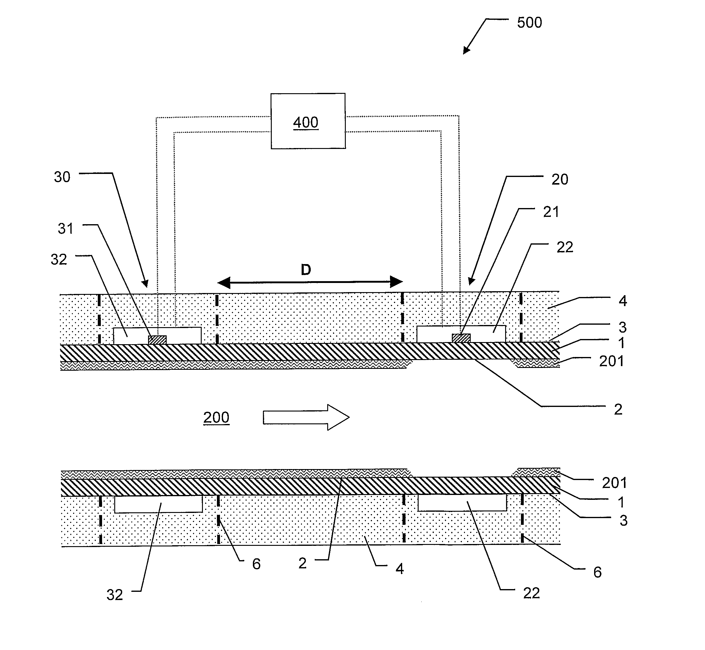
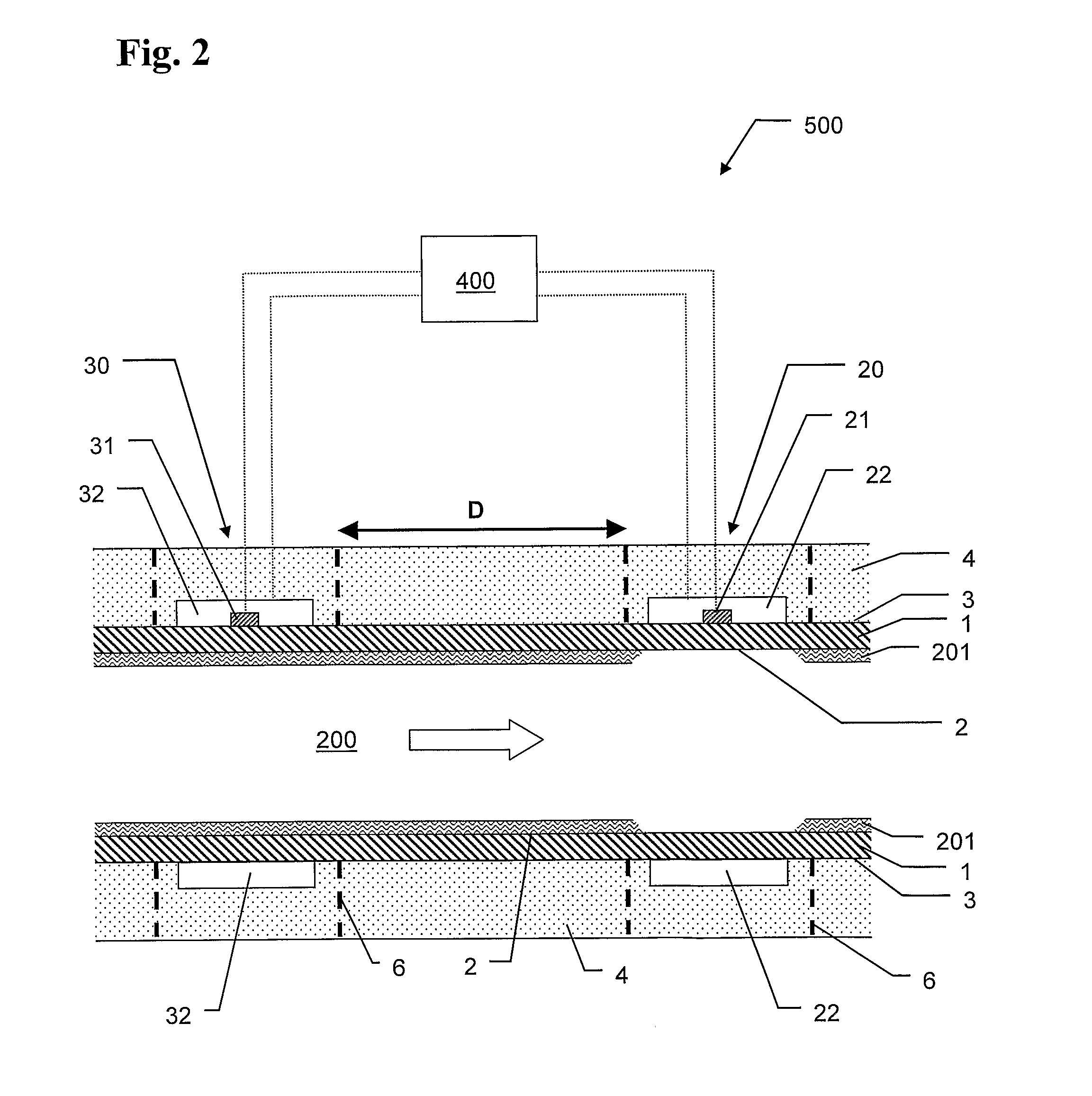
[0085]In alternative arrangement of the present invention as illustrated in FIG. 5, several measurement units 20, 30, 40 and 50 of the type described above are arranged at different locations along the pipeline. Further, a central processing means 400 (e.g. a computer device) is provided, which central processing means is adapted to receive local wax layer thickness data from all the measurement devices.

[0086]By including additional units of the second type 30 such as device 50, local deposit thicknesses may be measured at different location, based on a central calibration of one unit of the first type 20. By including additional units of the first type 20 such as unit 40, the reference data and calibration of other first type units, such as unit 20 may be monitored and controlled against malfunction, which might have serious effects. In addition, such additional first type units could alternatively also be used as second type units after a cleaning of the pipeline, if desired. Firs...


PUM


Abstract

The present invention concerns a method for measuring the thickness of any deposit of material on the inner wall of a structure conducting a fluid stream of hydrocarbons, the method comprising the steps of: applying a first heat pulse or continuous heating to at least one first section of the structure removing deposits on the inner wall of the first section of the structure; applying a second heat pulse to both the first section of the structure and at least one second section of the structure, the first and second sections being spaced apart, which heat pulse does not loosen any deposit of material in the second section; measuring the temperature of the wall of the structure or the fluid during the second heat pulse at both the first and second sections; and determining the thickness of any deposit of material on the inner wall of the structure at the second section based on the measured temperatures. The present invention also relates to a corresponding device and arrangement.

Description

FIELD OF THE INVENTION[0001]The present invention relates to a method of monitoring and measuring the thickness of any deposit of material, especially wax layers and wax build-up from a flow of hydrocarbons, on an inner wall of a structure, such as pipelines and process equipment for oil and gas.BACKGROUND[0002]Wax deposition at the inside wall of oil pipelines is a severe problem in today's oil production infrastructure. When warm oil flows through a pipeline with cold walls, wax will precipitate and adhere to the walls. This in turn will reduce the pipeline cross-sectional area, which without proper counter measures will lead to a loss of pressure and ultimately to a complete blockage of the pipeline.[0003]Existing technologies that deal with the problem by removing the deposits include:[0004]Pigging: Mechanical scraping off the wax from the pipe wall at regular intervals.[0005]Chemical inhibition: Addition of chemicals which prevent wax deposition.[0006]Direct Electrical Heating ...

Claims


Application Information

Patent Timeline
Patent Type & Authority Applications(United States)
IPC IPC(8): B08B7/00G01B21/08
CPCG01B21/085G01N17/008
Inventor AMUNDSEN, LENEHOFFMANN, RAINERSCHULLER, REIDAR
Owner DEN NORSKE STATS OLJESELSKAP AS
Why Eureka
Try Eureka