Vertically Moving Device

Active Publication Date: 2011-12-29
DAIFUKU CO LTD
View PDF25 Cites 7 Cited by
  • Summary
  • Abstract
  • Description
  • Claims
  • Application Information

AI Technical Summary

Benefits of technology

With the above-mentioned characteristic configuration, at least two wire-guiding rotating bodies provided to one longer side portion of the two longer side portions of the vertically movable platform are suspended by one of the looped portions, and at least two other of the wire-guiding rotating bodies pr

Problems solved by technology

However, in the vertically moving device described in Patent Document 1, only one of the four single-line is sometimes stretched longer than the other three due to changes that occu

Method used


Image

  • Vertically Moving Device
  • Vertically Moving Device
  • Vertically Moving Device

Examples


Embodiment Construction

The vertically moving device in accordance with the present invention is described next with reference to the drawings.

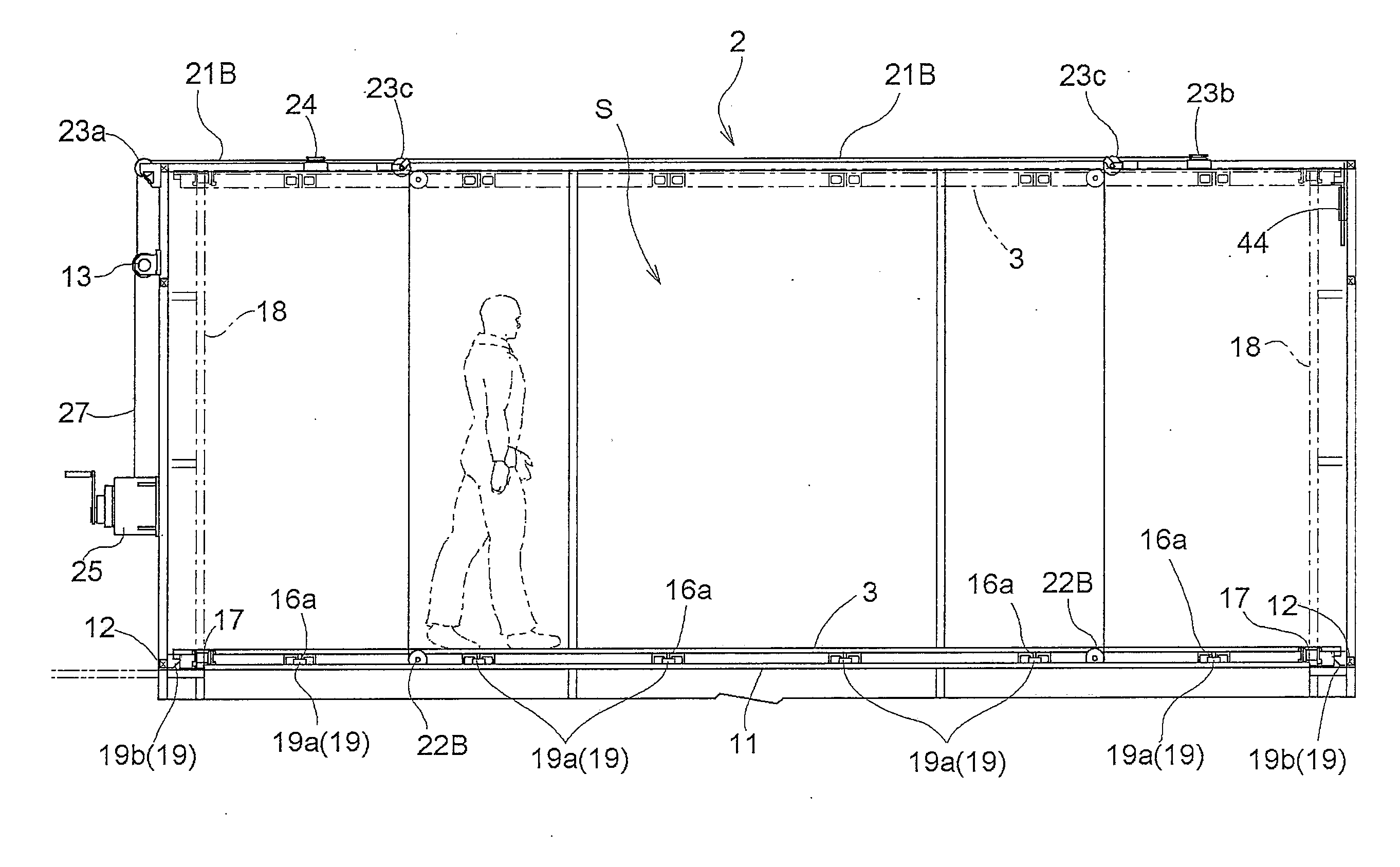
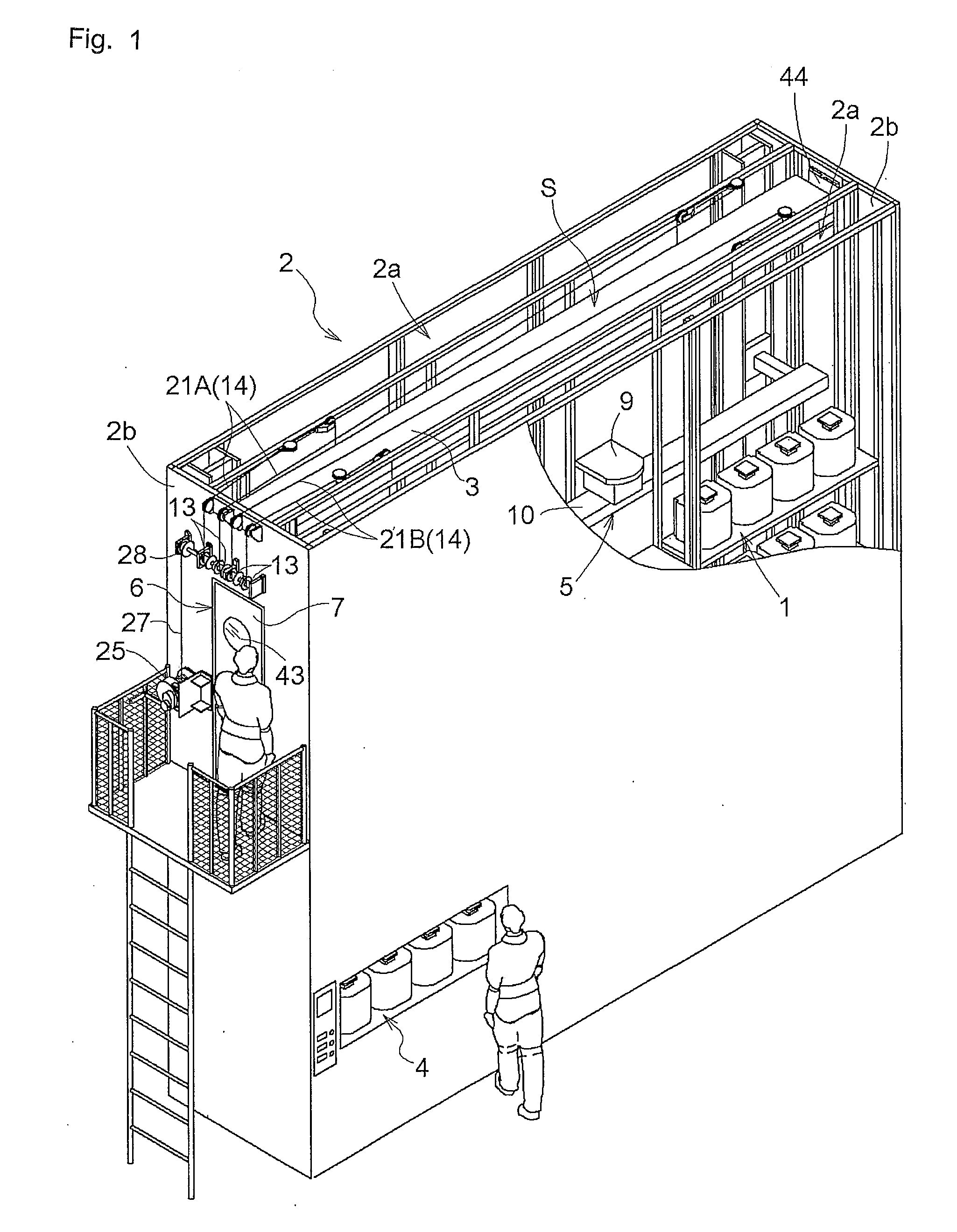
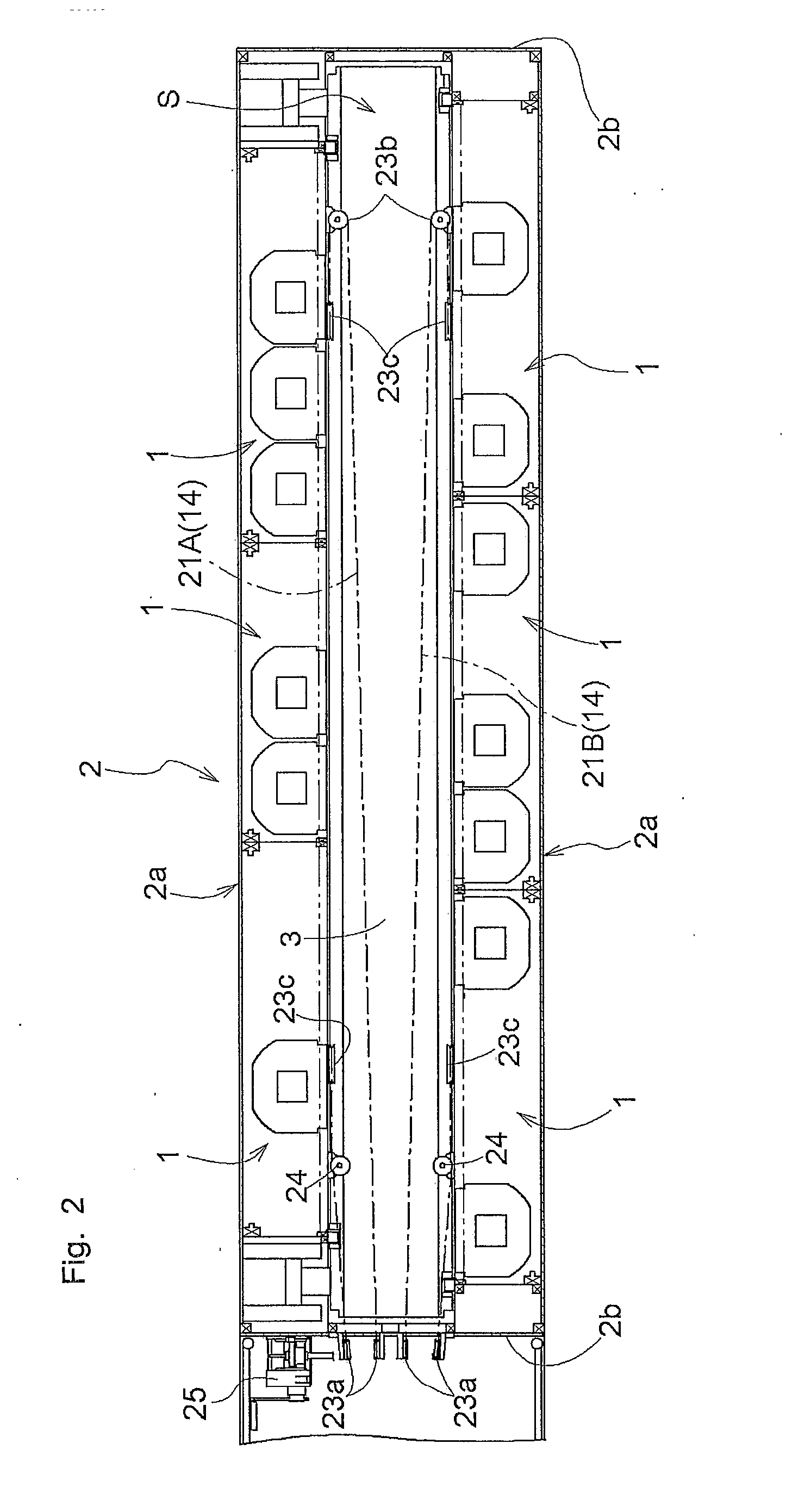
FIG. 1 is a perspective view of an article storage facility, and FIG. 2 is a plan view showing an upper portion of an article storage rack. As shown in FIGS. 1 and 2, the article storage facility includes an article storage rack 2, a vertically movable work platform 3, a transport device 5, and a vertically moving device. The article storage rack 2 is a structure which has predetermined dimensions in the vertical or height direction and in a horizontal or width direction, and includes a pair of storage rack portions 2a which face each other. The travel space S, described later, is defined between this pair of storage rack portions 2a. The article storage rack 2 has a plurality of storage units 1 which can store articles and which are arranged in the height direction and the width direction. And, the article storage rack 2a includes a plurality of article carrying-in...


PUM


Abstract

A vertically moving device includes a spool mechanism for spooling at least two wires that are fed out to form loops and a vertically movable platform suspended by looped portions of the at least two wires fed out from the spool mechanism. The vertically movable platform includes at least four wire-guiding rotating bodies over which the looped portions of the wires are run. And a looped portion of one of the wires is run over at least two of the wire-guiding rotating bodies, and a looped portion of the other of the wires is run over at least two other of the wire-guiding rotating bodies

Description

TECHNICAL FIELDThe present invention relates to a vertically moving device for vertically moving the vertically movable platform using wires.BACKGROUND ART Vertically moving devices operate a spool mechanism for spooling wires to vertically move a vertically movable platform to a predetermined height by adjusting the amount of the wires that are fed out from the spool mechanism. For example, in a vertically moving device described in Patent Document 1, four single-line wires spooled by a spool mechanism are connected to the four corners of a vertically movable platform which is rectangular in plan view. The height of the vertically movable platform is controlled by adjusting the amount of the wires fed out from the spool mechanism.Patent Document 1: Japanese Patent Application Publication No. H08-301410.DISCLOSURE OF THE INVENTIONHowever, in the vertically moving device described in Patent Document 1, only one of the four single-line is sometimes stretched longer than the other thre...

Claims


Application Information

Patent Timeline
IPC IPC(8): B66B11/04E04G3/32
CPCB65G1/02B66F7/02B65G2201/0297B65G1/00B66B11/0075
Inventor YOSHIOKA, HIDEO
Owner DAIFUKU CO LTD
Why Eureka
Try Eureka