Reactance Filter Having a Steep Edge

a technology of reactance filter and steep edge, which is applied in the direction of impedence network, electrical apparatus, piezoelectric/electrostrictive/magnetostrictive devices, etc., can solve the problems of increasing the ohmic loss of the reactance filter, requiring a larger chip area, or bringing about higher losses

Active Publication Date: 2011-12-29
SNAPTRACK
View PDF8 Cites 35 Cited by
  • Summary
  • Abstract
  • Description
  • Claims
  • Application Information

AI Technical Summary

Benefits of technology

[0010]A reactance filter of ladder-type or lattice arrangement known per se is proposed which comprises at least one series branch, which connects a signal input to a signal output. The reactance filter additionally has at least one parallel branch which, in the case of a ladder-type filter, branches off from the series branch with respect to ground or, in a lattice arrangement, interconnects the two series branches present here. A parallel resonator is arranged in each parallel branch and a plurality of series resonators are connected in series in each series branch in this reactance filter arrangement that is known to this extent. According to the invention, a capacitor is now connected in parallel with at least one of the series resonators. This parallel capacitor increases the effective static capacitance C0 of the series resonator and thereby changes the ratio of dynamic to static capacitance of the resonator. While the resonant frequency of the series resonator according to the formula:fr=12πC1Lis dependent exclusively on the dynamic capacitance Cl and the inductance of the resonator, the antiresonant frequency fa according to the formula:fa=fr1+C1C0additionally has a dependence on the ratio of dynamic to static capacitance. With the static capacitance increased according to the invention, the antiresonant frequency fa is also reduced, without the position of the resonant frequency simultaneously changing in this case. The coupling of the resonator is thus reduced.
[0011]Since the antiresonant frequency fa of the series resonators directly determines the position of the right-hand filter pole (“notch”), this reduced coupling brings about a shift in the pole toward the left to lower frequencies, even if the reduction of the coupling is performed at only one series resonator, or in any case not at all of the series resonators. The width of the passband remains virtually unchanged, since at least one of the series resonators but not all of the series resonators have a capacitor connected in parallel. As a result, the steepness of the right-hand passband edge is effectively increased, without appreciable losses in the bandwidth having to be accepted. The reactance filter arrangement specified makes it possible to increase the edge steepness by 1 dB / MHz, for example.
[0020]However, it is also possible to form the capacitor between the bottom electrode and a high-impedance layer of the acoustic mirror. This has the advantage that the capacitor can be formed for the most part or wholly below the resonator, without requiring additional area on the substrate. Such a capacitor can therefore be produced in a particularly simple manner and does not increase the basic area of the component, or increases it only to an insignificant extent.
[0024]In the case of a reactance filter according to the invention, a maximum effect with regard to a steeper upper edge is obtained if the capacitance of the capacitor is in the range of between 1% and 50%, and preferably in the range of 3%-30%, of the static capacitance of the resonator.

Problems solved by technology

Thus, the low temperature response and the high frequency accuracy predestine BAW filters for duplexer applications with a small separation between transmission and reception bands.
What is disadvantageous however, is that with this method the ohmic losses of the reactance filter also increase as a result of the number of interconnected series resonators.
What is disadvantageous about the known solutions for improving the edge steepness is, generally, that they either bring about higher losses or can be produced only with increased interconnection and production outlay.
A further disadvantage here is that for more resonators on the chip, a larger chip area is also necessary.

Method used


Image

  • Reactance Filter Having a Steep Edge
  • Reactance Filter Having a Steep Edge
  • Reactance Filter Having a Steep Edge

Examples


Embodiment Construction

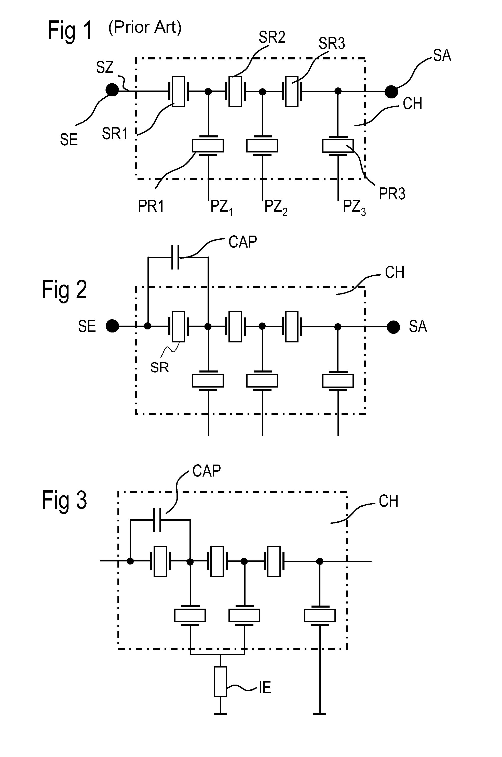
[0065]FIG. 1 shows a reactance filter having a ladder-type construction as known from the prior art. The filter is formed from resonators on a chip CH as carrier. A series branch SZ is connected between a signal input SE and a signal output SA. Proceeding from nodes of the series branch, here three parallel branches PZ are connected with respect to a fixed potential and, in particular, with respect to ground. A parallel resonator PR is arranged in each of the parallel branches PZ. The series branch SZ comprises a series interconnection of series resonators SR.

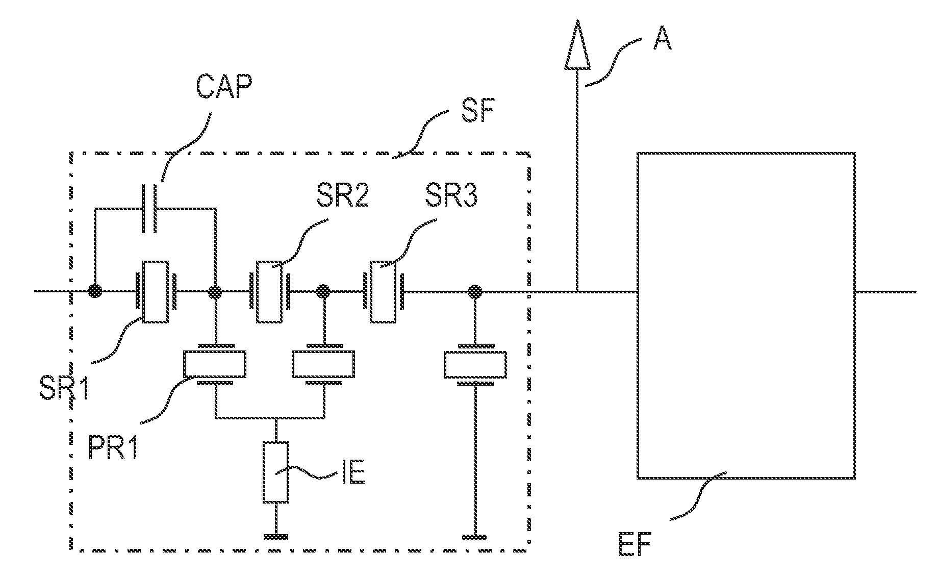
[0066]FIG. 2 shows a reactance filter, wherein a capacitor CAP is connected in parallel with a series resonator SR. Advantages are already obtained if a single one of the series resonators SR is connected in parallel with a capacitor, although such a capacitor can also bridge a plurality of series resonators in parallel (not illustrated in the figure). At least one of the series resonators remains unchanged relative thereto.

[00...


PUM


Abstract

A reactance filter includes a series branch that connects a signal input to a signal output. At least one parallel branch branches off from the series branch with respect to ground. A parallel resonator is arranged in each parallel branch. Two or more series resonators are connected in series in the series branch. A capacitor is connected in parallel with one of the series resonators in the series branch.

Description

[0001]This patent application is a national phase filing under section 371 of PCT / EP2010 / 052621, filed Mar. 2, 2010, which claims the priority of German patent application 10 2009 011 639.7, filed Mar. 4, 2009, each of which is incorporated herein by reference in its entirety.BACKGROUND[0002]Reactance filters having a bandpass filter character can be constructed from a ladder / lattice-like interconnection of impedance elements and, in particular, of resonators to form so-called ladder-type or lattice arrangements. The document EP 1 196 991 A1 discloses a ladder-type filter, for example, which is constructed from acoustic single-port resonators using SAW technology (SAW=Surface Acoustic Wave). The advantage of such a reactance filter is that, by means of the number and type of the elements used, it is possible to set the filter properties and, in particular to improve the stop band suppression.[0003]A reactance filter of ladder-type arrangement constructed from BAW resonators (BAW=Bul...

Claims


Application Information

Patent Timeline
Patent Type & Authority Applications(United States)
IPC IPC(8): H03H9/70H03H9/58
CPCH03H9/605H03H9/566H03H9/542H03H9/02007H03H9/02157H03H9/568H03H9/706
Inventor LINK, ANDREASMARKSTEINER, STEPHAN
Owner SNAPTRACK
Why Eureka
Try Eureka