
Quality of service control for mpls user access

Inactive Publication Date: 2011-12-29
ALCATEL-LUCENT USA INC
View PDF9 Cites 59 Cited by
  • Summary
  • Abstract
  • Description
  • Claims
  • Application Information

AI Technical Summary

Problems solved by technology

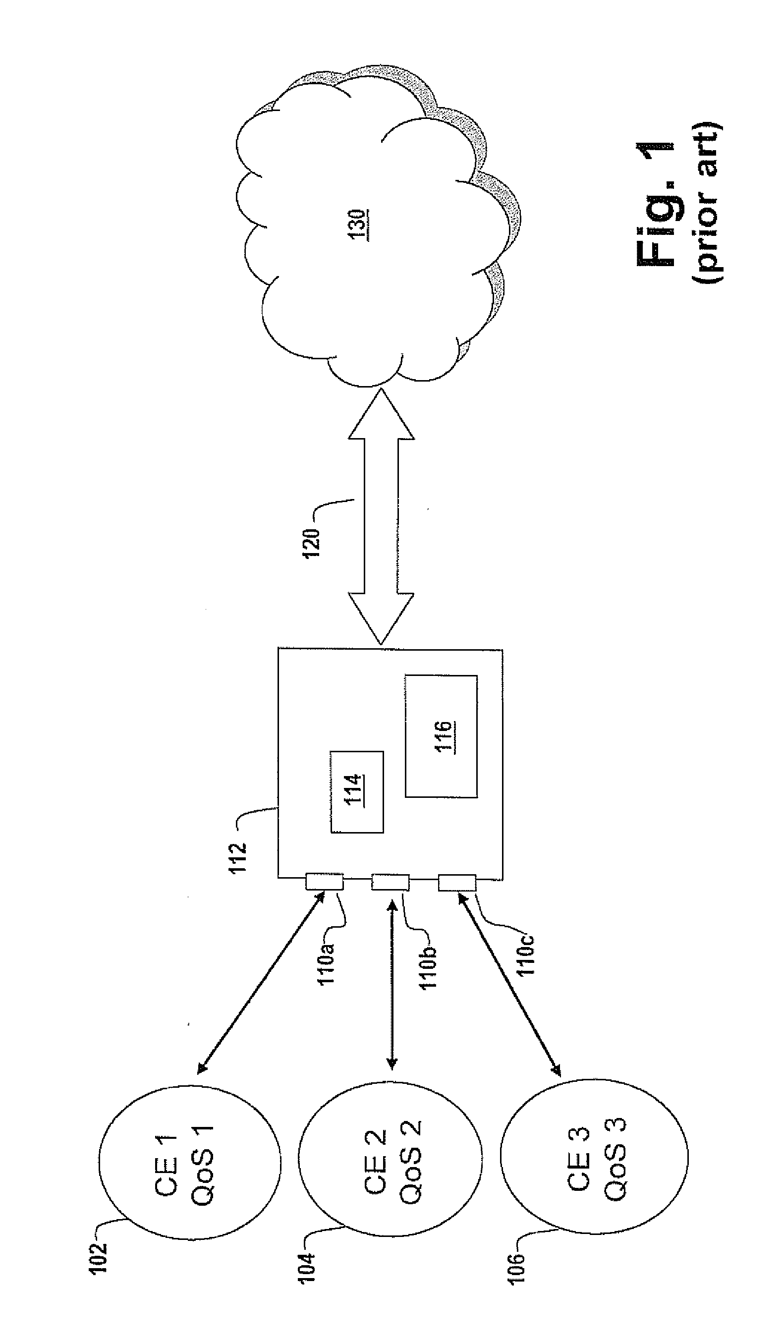
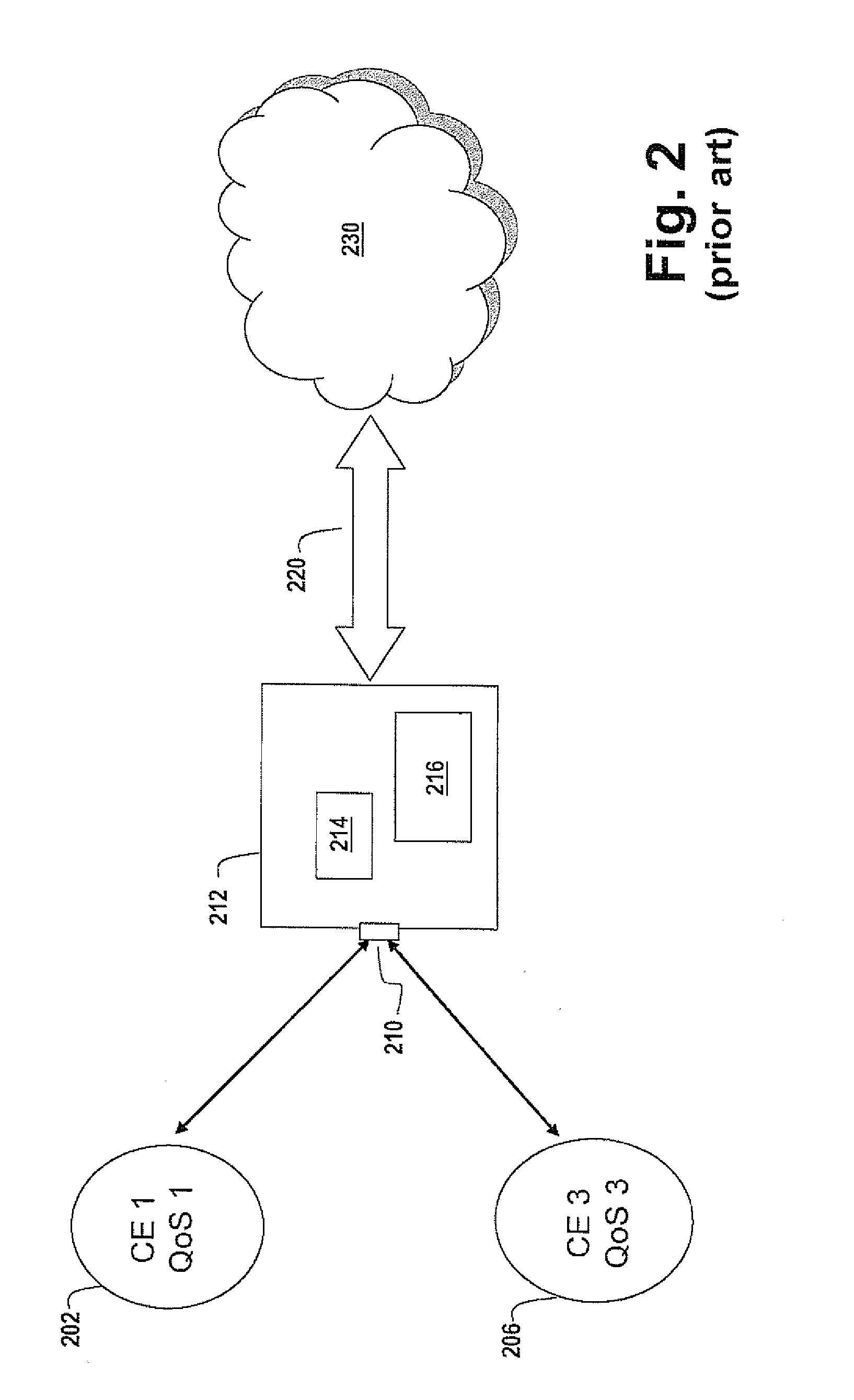
These QoS solutions are still at a high level of granularity and are not well suited to VPLS (Virtual Private LAN Service) environments where network layer 3 conditions may be unknown or irrelevant.

Method used


Image

  • Quality of service control for mpls user access
  • Quality of service control for mpls user access
  • Quality of service control for mpls user access

Examples


Embodiment Construction

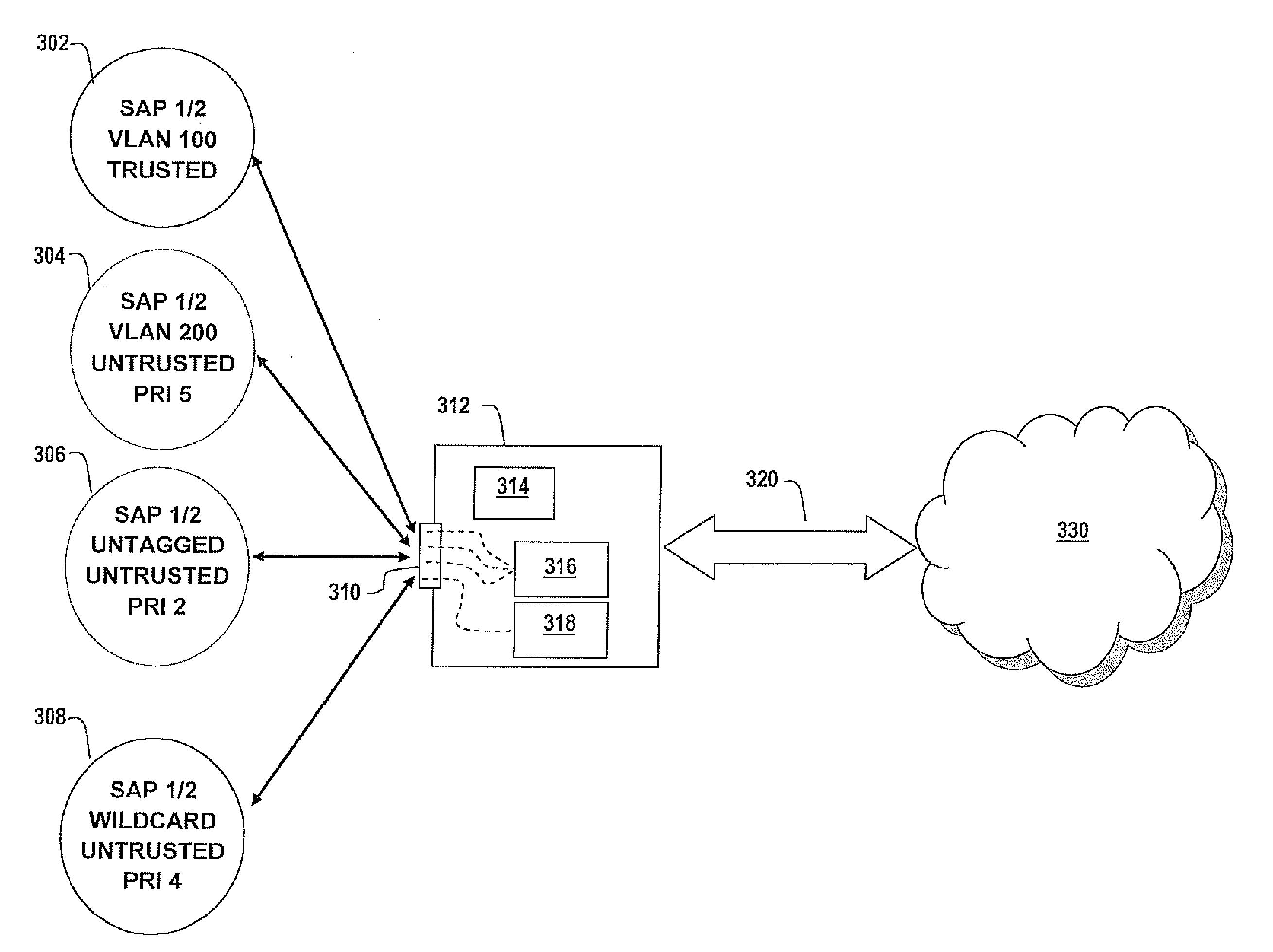
[0024]In the service model for an embodiment of the present invention, service edge routers are deployed at the provider edge.

[0025]Services, which are globally unique entities that refer to a type of connectivity service for either Internet or VPN connectivity, are provisioned on the service routers and transported across an IP and / or IP / MPLS provider core network in encapsulation tunnels created using MPLS label switched paths (LSPs). In terms of individual MPLS VPLS there is provided a way of setting priorities within a Forwarding Equivalency Class (FEC).

[0026]The service model uses logical service entities to construct a service. The logical service entities are designed to provide a uniform, service-centric configuration, management, and billing model for service provisioning. Some benefits of this service-centric design include:[0027]Many services can be bound to a single customer.[0028]QoS policies, filter policies, and accounting policies are applied to each service instead ...


PUM


Abstract

A method of associating a Quality of Service priority with a Service Access Point (SAP) is disclosed. The method provides for provision of Quality of Service priorities on incoming data packets as per the configuration specified in the SAP associated with the data packet. The method allows for a configuration in which the incoming packet will specify its own QoS priority. The provisioning of Quality of service on a per SAP basis allows for a finer granularity of prioritizing of packets over Quality of Service methods known in the art.

Description

FIELD OF THE INVENTION[0001]The invention relates to priority treatment of data packets and is particularly concerned with Quality of Service treatments of data packets within a Virtual Private LAN Service (VPLS) arriving at an ingress switch.BACKGROUND OF THE INVENTION[0002]The traffic engineering resource reservation control mechanism referred to as Quality of Service (QoS) refers to the ability to reliably provide different grades of service to different users, data flows, or applications under varying degrees of network loading. The grades of service may be specified by a variety of parameters, for example, maximum jitter, packet arrival order, packet dropping probability, required bit rate, bit error rate, or delay, among others.[0003]Historically, the Internet has evolved from a best-effort network wherein “Type of Service” and “Precedence” bits located in packet headers were not utilized, through ATM and Frame Relay layer 2 technologies which added QoS tags to the data.[0004]...

Claims


Application Information

Patent Timeline
IPC IPC(8): H04L12/56
CPCH04L12/4641H04L47/2433H04L45/50
Inventor CLARK, JOHN D.
Owner ALCATEL-LUCENT USA INC
Learn More