Display Tilting Device

a display and tilting technology, applied in the field can solve the problems of limited space, increased cost of display tilting devices, and difficulty in tilting the display apparatus upward and downward only using a small motor

Inactive Publication Date: 2012-01-05
GWAG SU MAN
View PDF9 Cites 7 Cited by
  • Summary
  • Abstract
  • Description
  • Claims
  • Application Information

AI Technical Summary

Benefits of technology

[0023]According to the display tilting apparatus of the present invention, a tilting plate and a rotary plate are rotatably installed at both sides of upper and lower link members which are symmetrical with respect to a horizontal line so as to keep a balanced state, and when the rotary plate rotates upward and downward to adjust a viewing angle, the upper and lower link members rotate the tilting plate in association with each other, and thus a viewing angle of a display panel can be adjusted regardless of the weight of the display apparatus using a motor of a small capacity.

Problems solved by technology

Since a large moment is loaded in the case of the display tilting apparatus, power of a large capacity should be used, and thus there is a limit in the space, and cost of the display tilting apparatus increases as much accordingly.
At this point, since the display apparatus mounted on the tilting plate 500 is considerably heavy, it is difficult to tilt the display apparatus upward and downward only using a small motor.
Contrarily, if a large motor is used, although it is possible to tilt the display apparatus, utilization of space is lowered, and it is impractical due to the high price.

Method used


Image

  • Display Tilting Device
  • Display Tilting Device
  • Display Tilting Device

Examples


Embodiment Construction

[0033]The preferred embodiments of a display tilting apparatus according to the present invention will be hereafter described in detail, with reference to the accompanying drawings.

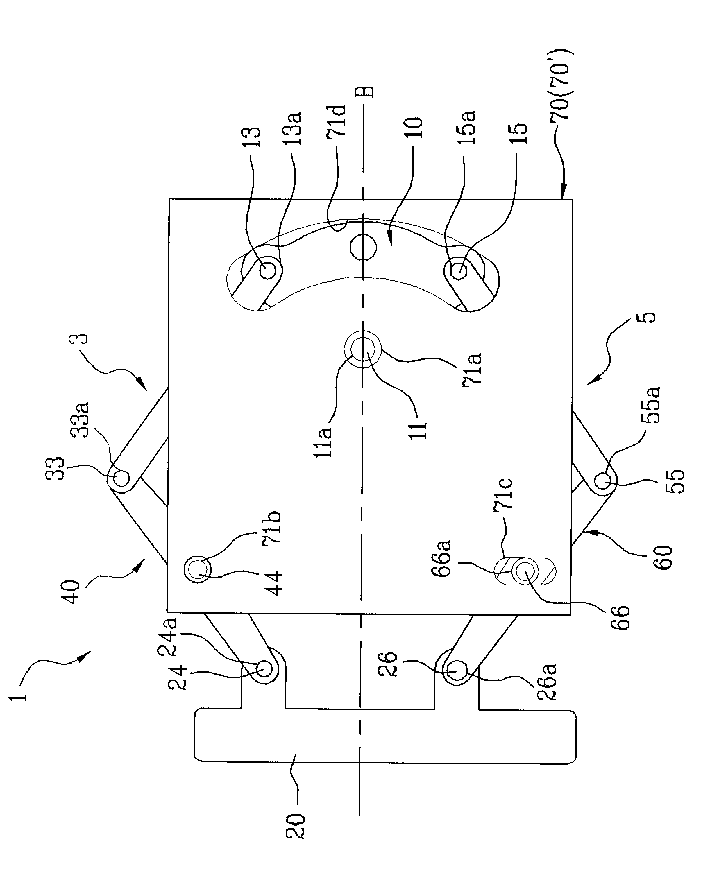
[0034]FIGS. 2 and 3 are conceptual views showing a display tilting apparatus according to the present invention, in which FIG. 2 shows a view mounting a fixing plate, and FIG. 3 shows a view dismounting the fixing plate.

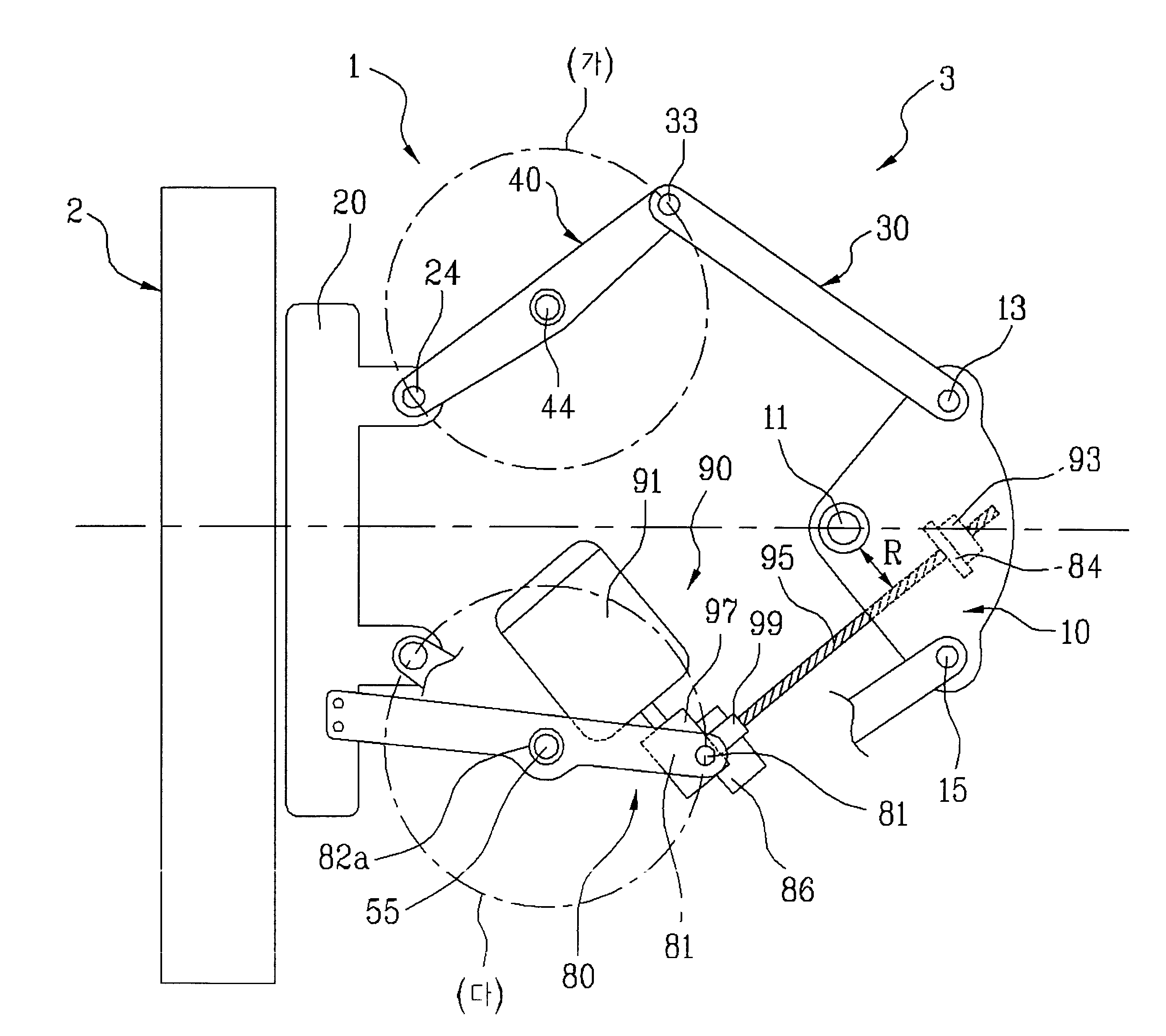
[0035]First, referring to FIG. 3, the display tilting apparatus 1 according to the present invention comprises a rotary plate 10 rotating around an eccentric shaft 11, an upper link member 3 installed at an upper part of the rotary plate 10 to rotate the rotary plate 10 around the eccentric shaft 11, a lower link member 5 installed at a lower part of the rotary plate 10 to rotate the rotary plate 10 around the eccentric shaft 11, and a tilting plate 20 pivotably installed at the other end of the upper and lower link members 3 and 5.

[0036]The tilting plate 20 is supported by the actions of ...


PUM


Abstract

The present invention relates to a display tilting apparatus, and more specifically, to a display tilting apparatus, in which an eccentric shaft and a rotating shaft are rotatably installed at both ends of upper and lower link members having a symmetrical structure, and a display apparatus mounted on a tilting plate can be tilted by rotating upward and downward using a motor of a small capacity regardless of the weight of the display apparatus through interactions between the upper and lower link members.
The display tilting apparatus for rotating the display apparatus upward and downward according to the present invention comprises: a rotary plate rotating upward and downward centering on one eccentric shaft; an upper link member connected to an upper part of the rotary plate, for rotating the rotary plate; a lower link member connected to a lower part of the rotary plate, for rotating the rotary plate; a tilting plate rotating upward and downward, for mounting the display apparatus, in which the upper link member is connected to an upper part, and the lower link member is connected to a lower part; and a fixing plate for rotatably supporting the eccentric shaft of the rotary plate and an upper fixing shaft and a lower fixing shaft installed in a middle of the upper link member and the lower link member.

Description

TECHNICAL FIELD[0001]The present invention relates to a display tilting apparatus, and more specifically, to a display tilting apparatus, in which a rotary plate rotating around an eccentric shaft is installed at one end of upper and lower link members which are symmetrical with respect to a horizontal line, and a tilting plate for mounting a display panel is pivotably installed at the other end of the upper and lower link members so as to keep a balanced state, so that a viewing angle of the display panel can be adjusted up and down by rotating the rotary plate clockwise or counterclockwise using a motor of a small capacity.BACKGROUND ART[0002]Generally, a display stand is provided with an apparatus for controlling a viewing angle of a display panel by lifting up and down or pivoting left and right, and up and down a display apparatus such as a television or a monitor.[0003]A display tilting apparatus changes a viewing angle of a display panel vertically by pivoting the display app...

Claims


Application Information

Patent Timeline
Patent Type & Authority Applications(United States)
IPC IPC(8): F16M13/02
CPCF16M11/04F16M11/10F16M2200/063F16M11/38F16M2200/041F16M11/18G06F1/16G06F1/166H04N5/655
Inventor GWAG, SU-MAN
Owner GWAG SU MAN
Why Eureka
Try Eureka