
Method and system for blocker detecton and automatic gain control

a detection method and automatic gain control technology, applied in the field of communication, can solve the problems of increasing difficulty in dealing with noise in communication devices, increasing difficulty in addressing interference in communication devices, and increasing complexity of devices and fabrication technologies

Active Publication Date: 2012-01-05
AVAGO TECH INT SALES PTE LTD
View PDF29 Cites 20 Cited by
  • Summary
  • Abstract
  • Description
  • Claims
  • Application Information

AI Technical Summary

Benefits of technology

[0012]FIG. 3A is a flow chart illustrating an exemplary soft decision technique for controlling gain based on strength of a blocker signal, in accordance with an embodiment of the invention.
[0013]FIG. 3B is a flow chart illustrating an exemplary hard decision technique for controlling gain based on strength of a blocker signal, in accordance with an embodiment of the invention.
[0014]FIG. 3C is a flow chart illustrating an exemplary hard decision technique for controlling gain based on strength of a blocker signal in a 2G wireless system, in accordance with an embodiment of the invention.

Problems solved by technology

As devices and fabrication technologies get smaller and more complex, dealing with noise in communication devices becomes increasingly difficult.
Additionally, as the number of wireless communication devices and wireless communication protocols in use continues to increase, dealing with interference in the communication devices also becomes increasingly difficult.
Compounding the difficulties facing system designers is that conventional techniques for mitigating the effects of interference are often in contention with techniques for improving the noise figure of the communication device.

Method used


Image

  • Method and system for blocker detecton and automatic gain control
  • Method and system for blocker detecton and automatic gain control
  • Method and system for blocker detecton and automatic gain control

Examples


Embodiment Construction

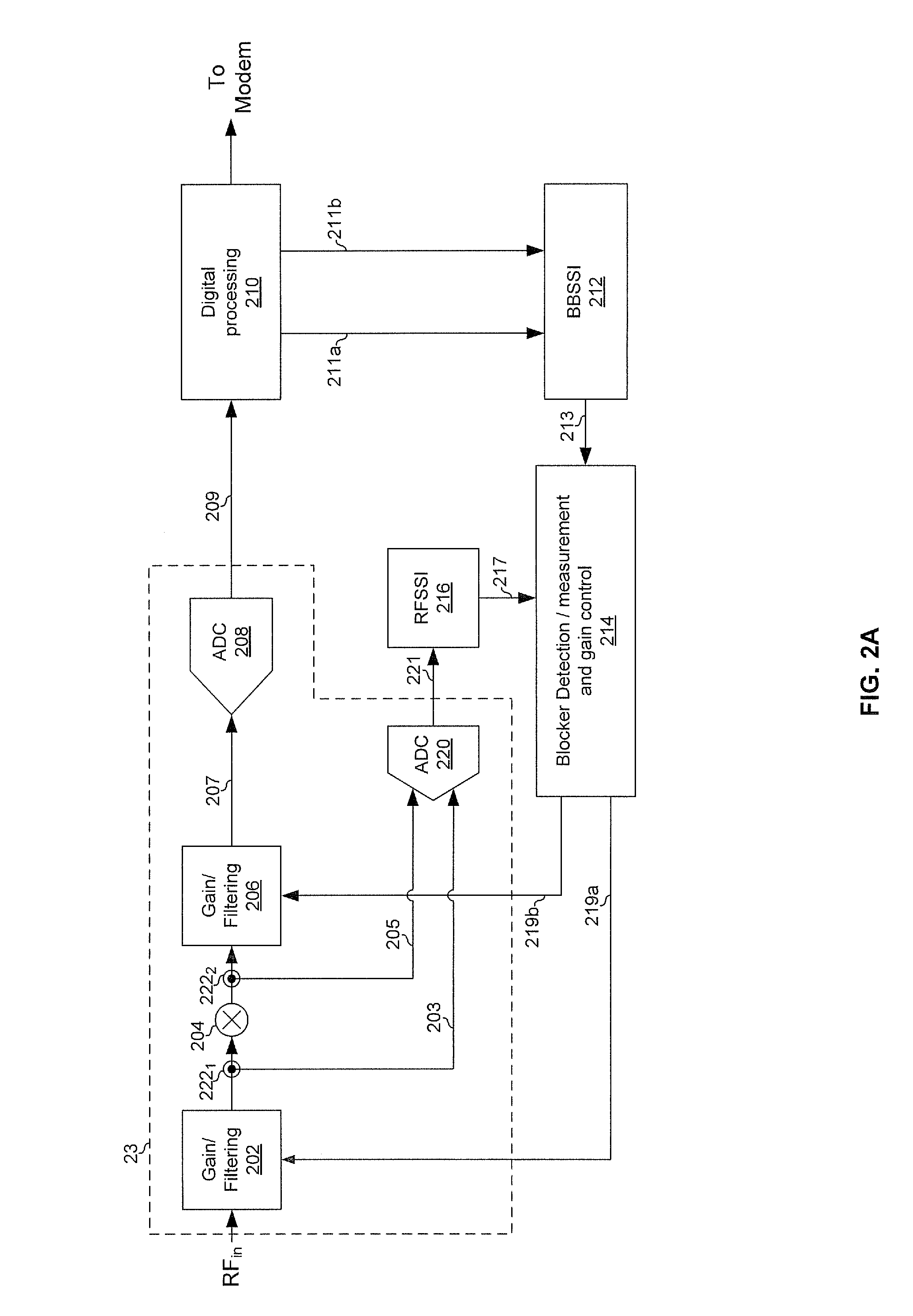
[0015]Certain embodiments of the invention may be found in a method and system for blocker detection and automatic gain control. In various embodiments of the invention, a communication device may generate a first signal strength indication based on a strength of a received signal at a point in the analog front-end of the communication device. The communication device may generate a second signal strength indication based on a strength of the received signal at a point in a digital processing module of the communication device. The points in the analog front-end may be, respectively, an input and an output of a down-conversion mixer. The points in the digital processing module may be, respectively, an output of an analog-to-digital converter and an output of a channel selection filter.

[0016]The communication device may control, utilizing the first signal strength indication and the second signal strength indication, a gain of one or more components of the communication device. Gener...


PUM


Abstract

Aspects of a method and system for integrated blocker detection and automatic gain control are provided. In this regard, a communication device may generate one or more first signal strength indications based on a strength of a received signal at a first point in the analog front-end of the communication device. The communication device may generate one or more second signal strength indications based on a strength of the received signal at a second point in a digital processing module of the communication device. The first point in the analog front-end may be an input or an output of a down-conversion mixer. The second point in the digital processing module may be an output of an analog-to-digital converter or an output of a channel selection filter. The communication device may control, utilizing the first signal strength indication(s) and the second signal strength indication(s), a gain of one or more components of the communication device.

Description

CROSS-REFERENCE TO RELATED APPLICATIONS / INCORPORATION BY REFERENCE[0001]This patent application makes reference to, claims priority to and claims benefit from U.S. Provisional Patent Application Ser. No. 61 / 360,793 filed on Jul. 1, 2010.[0002]Each of the above identified applications is hereby incorporated herein by reference in its entirety.FIELD OF THE INVENTION[0003]Certain embodiments of the invention relate to communications. More specifically, certain embodiments of the invention relate to a method and system for blocker detection and automatic gain control.BACKGROUND OF THE INVENTION[0004]As devices and fabrication technologies get smaller and more complex, dealing with noise in communication devices becomes increasingly difficult. Additionally, as the number of wireless communication devices and wireless communication protocols in use continues to increase, dealing with interference in the communication devices also becomes increasingly difficult. Compounding the difficultie...

Claims


Application Information

Patent Timeline
Patent Type & Authority Applications(United States)
IPC IPC(8): H04B7/00
CPCH04W52/245H04B17/318H04W52/52H04W52/246
Inventor AHMED, WALIDLEUNG, JOHNGEORGANTAS, THEODOROSDAMGAARD, MORTENSOLLENBERGER, NELSON
Owner AVAGO TECH INT SALES PTE LTD
Learn More