Screw fixation system

a screw and fixation system technology, applied in the field of screw fixation system, to achieve the effect of facilitating the repair of fractured bones

Inactive Publication Date: 2012-01-05
TOBY ORTHOPAEDICS
View PDF5 Cites 41 Cited by
  • Summary
  • Abstract
  • Description
  • Claims
  • Application Information

AI Technical Summary

Benefits of technology

[0009]The present invention in a further preferred embodiment contemplates a screw fixation system for use in an orthopedic procedure including an orthopedic implant, a bone screw, and a screw fixing element. The orthopedic implant is formed at least in part by a wire loop defining an opening. The bone screw has a trailing end, a leading end opposite the trailing end, a head portion proximate the trailing end, and a shaft portion extending from the head portion to the leading end. The head portion includes an exterior surface, and the shaft portion includes threads adapted to engage bone. The screw fixing element has a body including a channel adapted to receive a portion of the wire loop, and an aperture formed through the body. The aperture has a central axis extending through the center of the aperture, and the aperture includes an engagement surface adapted to engage the exterior surface of the head portion. Progressive engagement of the engagement surface and the exterior surface causes the screw fixing element to expand against the portion of the wire loop to fix the bone screw and the orthopedic implant relative to one another. Furthermore, when the bone screw and the orthopedic implant are fixed in position relative to one another, the screw fixing element covers more than half of a cross-sectional perimeter of the wire loop in a plane aligned with and extending through the central axis of the aperture.
[0010]The present invention in a still further preferred embodiment contemplates a method for facilitating repair of a fractured bone. The method includes the acts of providing an orthopedic implant formed at least in part by a wire loop defining an opening; providing a bone screw having a trailing end, a leading end opposite the trailing end, a head portion proximate the trailing end, and a shaft portion extending from the head portion to the leading end; providing a screw fixing element having a body including an upper surface, an opposite lower surface, an aperture extending between the upper and lower surfaces, and a channel adapted to receive a portion of the orthopedic implant adjacent the at least one opening, the aperture having a central axis extending through the center of the aperture, and the channel being provided proximate at least a portion of the perimeter of the body in a plane perpendicular to the central axis; introducing the screw fixing element into the opening of the wire loop, and inserting a portion of the wire loop into the channel of the screw fixing element; positioning the screw fixing element received in the opening of the wire loop adjacent a fractured bone; inserting the bone screw through the aperture of the screw fixing element and into the fractured bone; engaging threads on the head of the screw with threads in the aperture of the screw fixing element; tightening the bone screw against the screw fixing element to expand the screw fixing element against the portion of the wire loop received in the channel to fix the bone screw and the orthopedic implant relative to one another; and covering more than half of a cross-sectional perimeter of the wire loop in a plane aligned with and extending through the central axis of the aperture with the screw fixing element.

Problems solved by technology

Given the inherent malleability of a surgical wire, however, the possibility exists that further deformation of the wire will cause disengagement thereof from a head of a fastener.

Method used


Image

  • Screw fixation system
  • Screw fixation system
  • Screw fixation system

Examples


Embodiment Construction

[0018]The following description is intended to be representative only and not limiting, and many variations can be anticipated according to these teachings. Reference will now be made in detail to the preferred embodiments of this invention, examples of which are illustrated in the accompanying drawings.

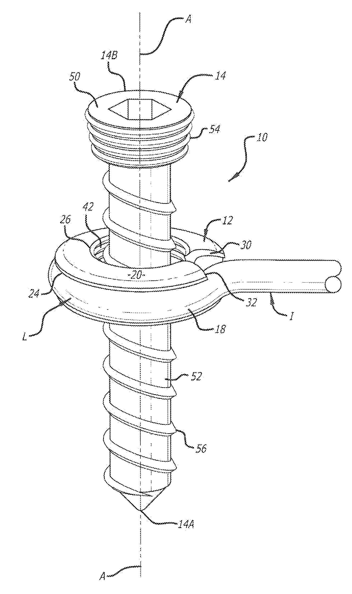
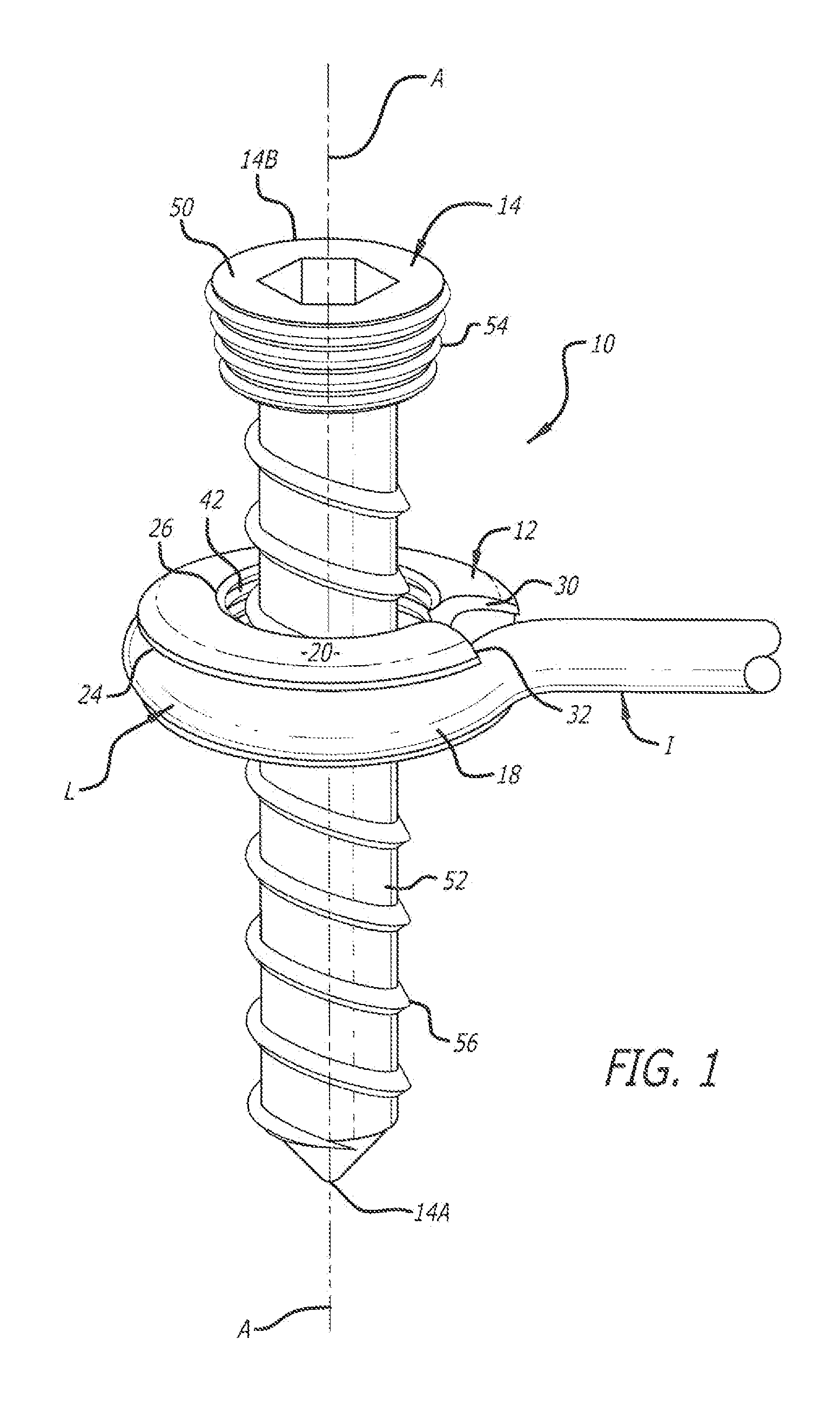
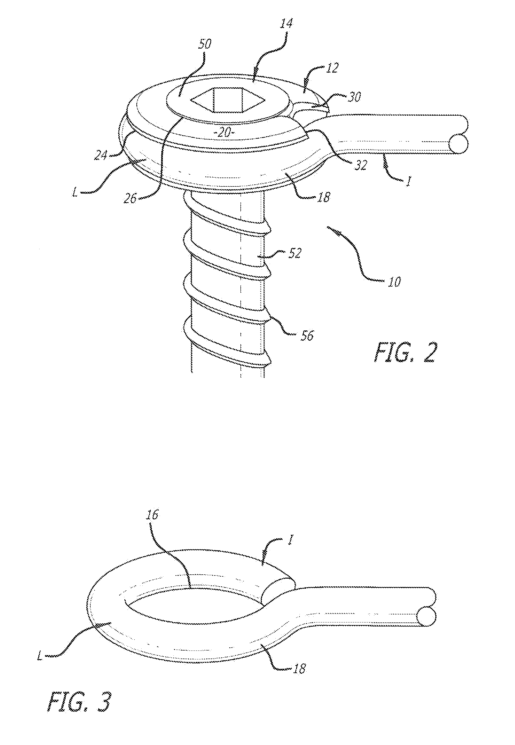
[0019]FIGS. 1 and 2 depict one preferred embodiment of the screw fixation system according to the present invention. The screw fixation system is generally indicated by the numeral 10 in FIGS. 1 and 2. As depicted in FIGS. 1 and 2, the screw fixation system 10 includes a screw fixing element 12, a fastener 14, and an orthopedic implant I. Furthermore, while fastener 14 depicted in FIGS. 1 and 2 is a bone screw including threads for engaging bone (and is hereinafter referred to as bone screw 14), fastener 14, for example, can instead include ratchets (not shown) for engaging bone.

[0020]Orthopedic implant I is provided for implantation into the human body, and, for example, can be used...


PUM


Abstract

A screw fixation system serves to facilitate attachment of an orthopedic implant to a fractured bone to facilitate healing thereof. The screw fixation system includes the orthopedic implant, a bone screw, and a screw fixing element. The orthopedic implant includes an opening formed thereby. The screw fixing element has a body including an aperture extending between upper and lower surfaces thereof, and a channel adapted to receive a portion of the orthopedic implant adjacent the opening. When the portion of the orthopedic implant is received in the channel and the bone screw is inserted into the aperture, engagement of at least a portion of threads formed on a head of the bone screw and threads formed in the aperture expands the screw fixing element against the orthopedic implant to fix the bone screw and the orthopedic implant relative to one another.

Description

[0001]The present application claims the benefit of provisional Application No. 61 / 398,455, filed Jun. 25, 2010, which is incorporated by reference herein.BACKGROUND OF THE INVENTION[0002]1. Field of the Invention[0003]The present invention is generally related to a system and method thereof for use in fixing a bone screw in relation to an orthopedic implant. More particularly, the present invention is related to a screw fixing element for securing a bone screw and an orthopedic implant in relation to one another. More specifically, the present invention is related to a screw fixing element for facilitating fixation of a bone screw at a predetermined angle relative to an orthopedic implant.[0004]2. Description of the Prior Art[0005]Surgical wires previously have been used by surgeons in repairing fractured bone. As such, the surgical wires have been used as orthopedic implants used in fixing fractured bone portions relative to one another to facilitate healing of the fractured bone....

Claims


Application Information

Patent Timeline
Patent Type & Authority Applications(United States)
IPC IPC(8): A61B17/86
CPCA61B17/68A61B17/8695A61B17/8605A61B17/8047
Inventor GONZALEZ-HERNANDEZ, EDUARDO
Owner TOBY ORTHOPAEDICS
Why Eureka
Try Eureka