Screw thread placement in a porous medical device

a technology of porous medical devices and screw threads, applied in the field of orthopedic implants, can solve the problem of orthopedic implants having a reduced surface area available for adjacent engagemen

Inactive Publication Date: 2010-12-30
ZIMMER INC
View PDF17 Cites 119 Cited by
  • Summary
  • Abstract
  • Description
  • Claims
  • Application Information

AI Technical Summary

Benefits of technology

[0008]According to another embodiment of the present invention, a porous orthopedic implant is provided to receive a threaded fastener. The porous orthopedic implant includes a first, porous component that defines an outer surface of the porous orthopedic implant for contacting a patient's bone, and a second compone

Problems solved by technology

However, compared to a solid structure, the high porosity causes the orthopedic implan

Method used


Image

  • Screw thread placement in a porous medical device
  • Screw thread placement in a porous medical device
  • Screw thread placement in a porous medical device

Examples


Embodiment Construction

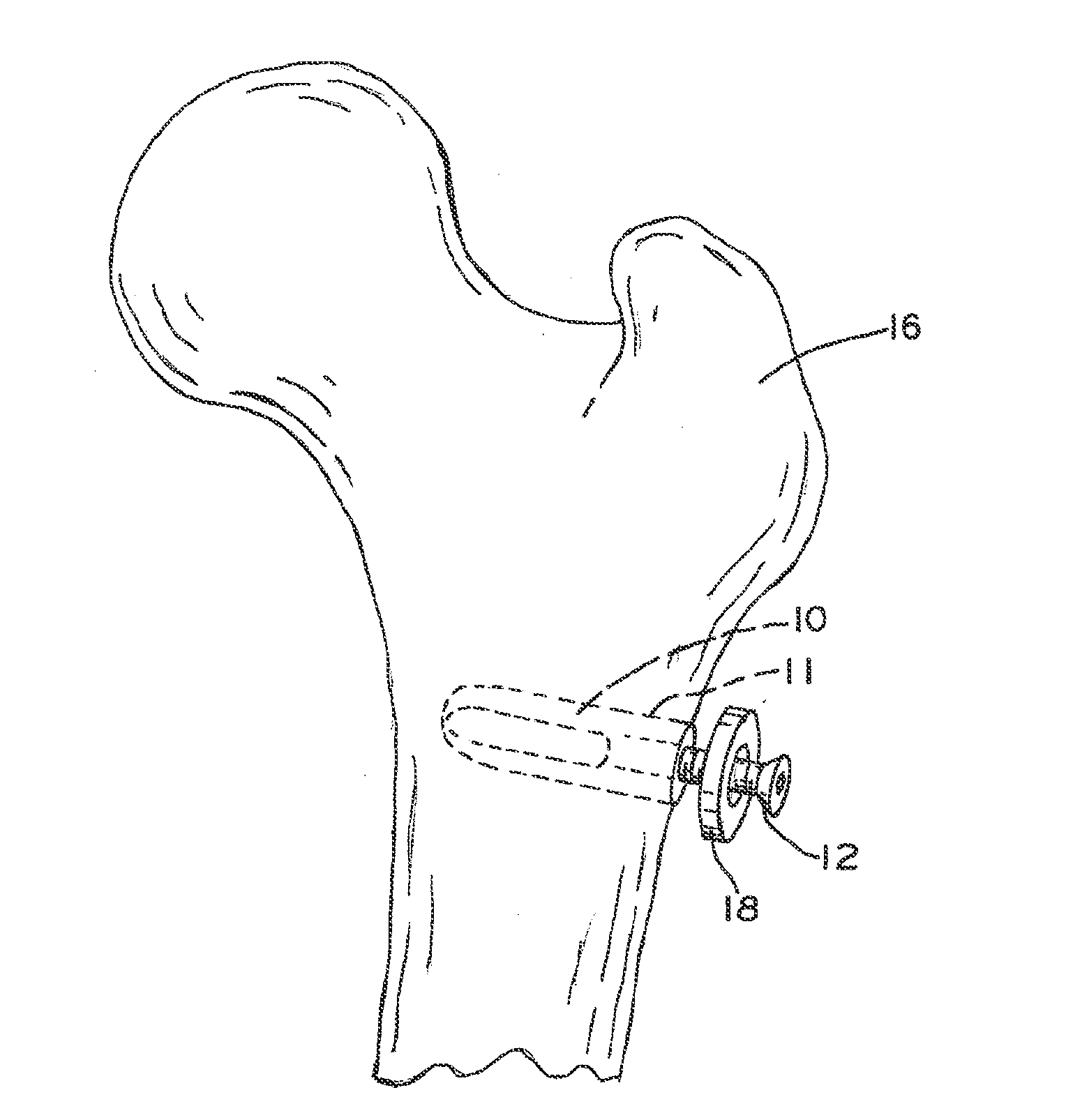
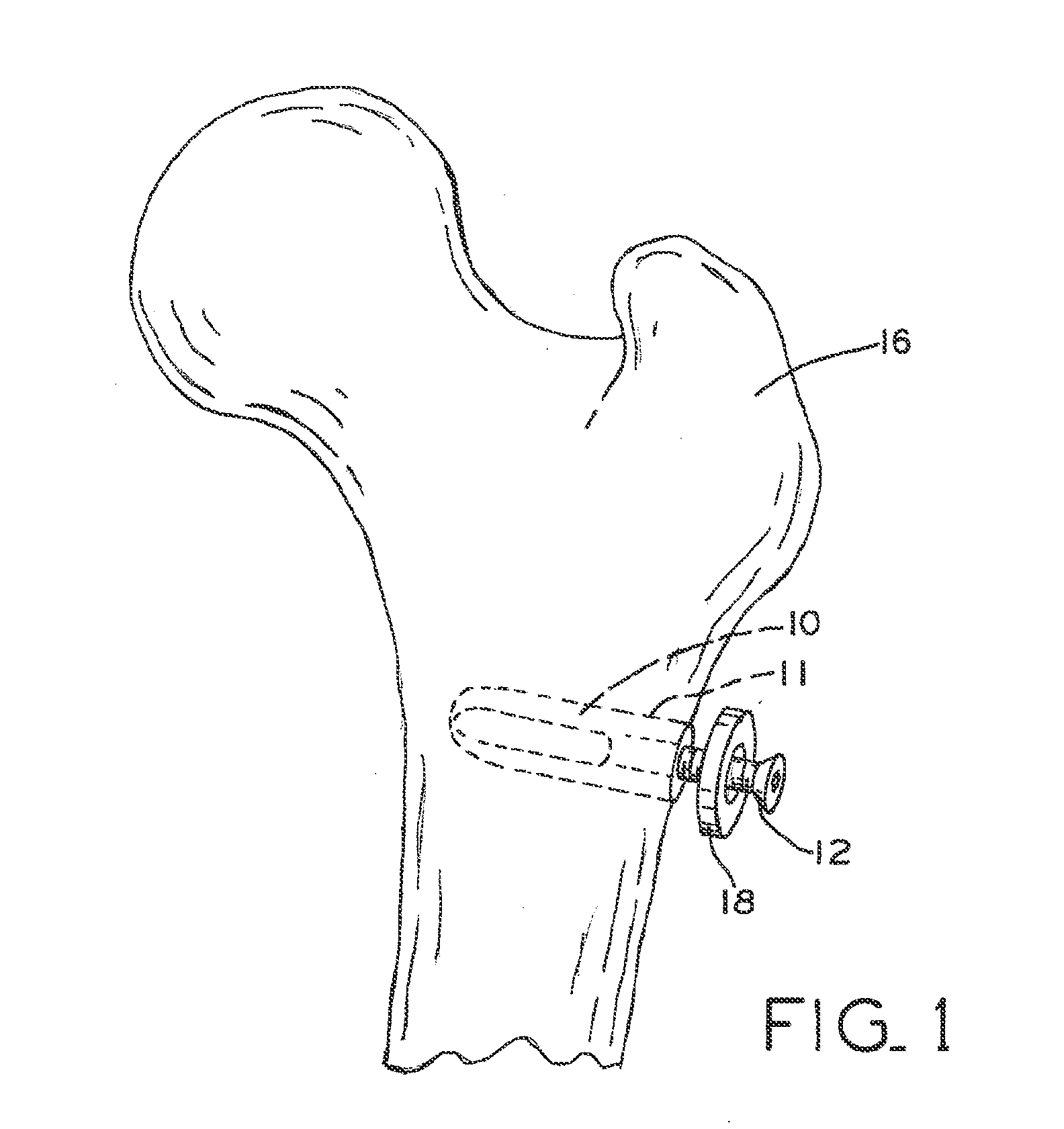
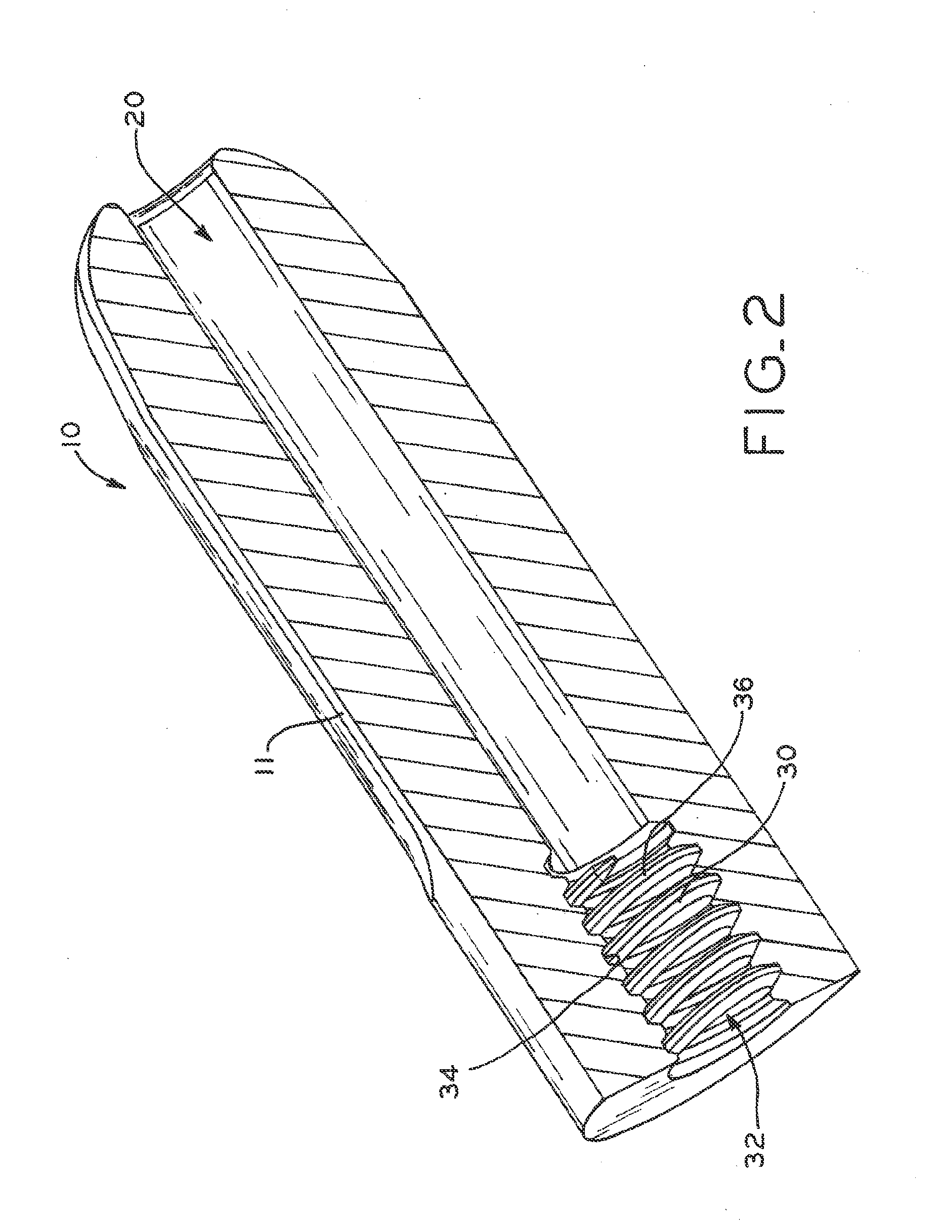
[0020]FIG. 1 depicts an orthopedic implant in the form of anchor 10. Anchor 10 is shown (in phantom) implanted in a patient's femur 16 such that outer surface 11 of anchor 10 contacts bone and / or soft tissue. Anchor 10 is configured to receive an externally threaded fastener, such as a bolt or screw 12. Coupling a threaded fastener, such as screw 12, to anchor 10 may provide a secure, locked engagement between anchor 10 and another orthopedic implant and / or between anchor 10 and a patient's bone, for example. Although the orthopedic implant is described and depicted herein as anchor 10, the orthopedic implant of the present disclosure may be any suitable implant configured to receive an externally threaded fastener, including, for example, a tibial component (such as a tibial augment component), a femoral component, an acetabular component, or a spinal fusion component (such as a posterior lumbar interbody fusion implant).

[0021]Anchor 10 may be used in a variety of applications. For...


PUM

PropertyMeasurementUnit
Densityaaaaaaaaaa
Poreaaaaaaaaaa

Abstract

Methods are provided for manufacturing an internal thread in a porous orthopedic implant, such as an orthopedic anchor. In one embodiment, the internal thread is formed in the orthopedic implant by bonding a pre-formed, internally threaded component to the orthopedic implant. In another embodiment, the internal thread is formed in the orthopedic implant by bonding a solid plug to the orthopedic implant or forming a surface coating on the orthopedic implant and then machining the solid plug or surface coating.

Description

CROSS REFERENCE TO RELATED APPLICATION[0001]This application claims priority from U.S. Provisional Patent Application Ser. No. 61 / 221,614, entitled “SCREW THREAD PLACEMENT IN A POROUS MEDICAL DEVICE,” filed Jun. 30, 2009, the disclosure of which is hereby expressly incorporated by reference herein in its entirety.BACKGROUND[0002]1. Field of the Invention[0003]The present invention relates to orthopedic implants. More particularly, the present invention relates to placement of internal screw threads in porous orthopedic implants.[0004]2. Description of the Related Art[0005]Orthopedic implants include porous bone contacting surfaces to encourage bone ingrowth. Bone ingrowth promotes increased fixation of the orthopedic implant to adjacent bone tissue. However, compared to a solid structure, the high porosity causes the orthopedic implant to have a reduced surface area available for engaging adjacent orthopedic components. The high porosity also impacts the ability to machine the ortho...

Claims


Application Information

Patent Timeline
IPC IPC(8): A61F2/28B23P19/04
CPCA61F2/0077Y10T29/49826A61F2/30749A61F2/3094A61F2/34A61F2/4455A61F2002/30013A61F2002/30289A61F2002/30797A61F2002/30878A61F2002/3092A61F2002/30922A61F2002/30967A61F2002/3412A61F2230/0091A61F2240/001A61F2250/0024A61F2310/00161A61F2310/00395A61F2310/00491A61F2310/00544A61F2/30721A61F2002/30011
Inventor MOHAMMED, MOBARAKH
Owner ZIMMER INC
Why Eureka
Try Eureka