Supercharge Your Innovation With Domain-Expert AI Agents!

Power Control System and Method

a power control system and power technology, applied in the field of power control methods and apparatuses, can solve the problems of significant cost to power an electronic device in this slow drain state, and reduce the power consumption of the electronic device to zero,

Inactive Publication Date: 2012-01-05
CHOMATIL VIJAYAN
View PDF2 Cites 2 Cited by
  • Summary
  • Abstract
  • Description
  • Claims
  • Application Information

AI Technical Summary

Benefits of technology

[0018]The apparatus may include a transmitter, the apparatus operable therewith to transmit a code to control the particular electronic device connected to the particular power port. In this instance, the controller may be operable to transmit the code for controlling the particular electronic device and therewith turn the particular electronic device on a predetermined time after the particular power port is switched to the on state.

Problems solved by technology

The cost to power an electronic device in this slow drain state can be significant and for many electronic devices can exceed $30 per year.
Remotes are extremely convenient for powering an electronic device on or off, however they do not address the problem of completely powering off an electronic device thereby reducing its power consumption to zero.

Method used


Image

  • Power Control System and Method
  • Power Control System and Method
  • Power Control System and Method

Examples


Embodiment Construction

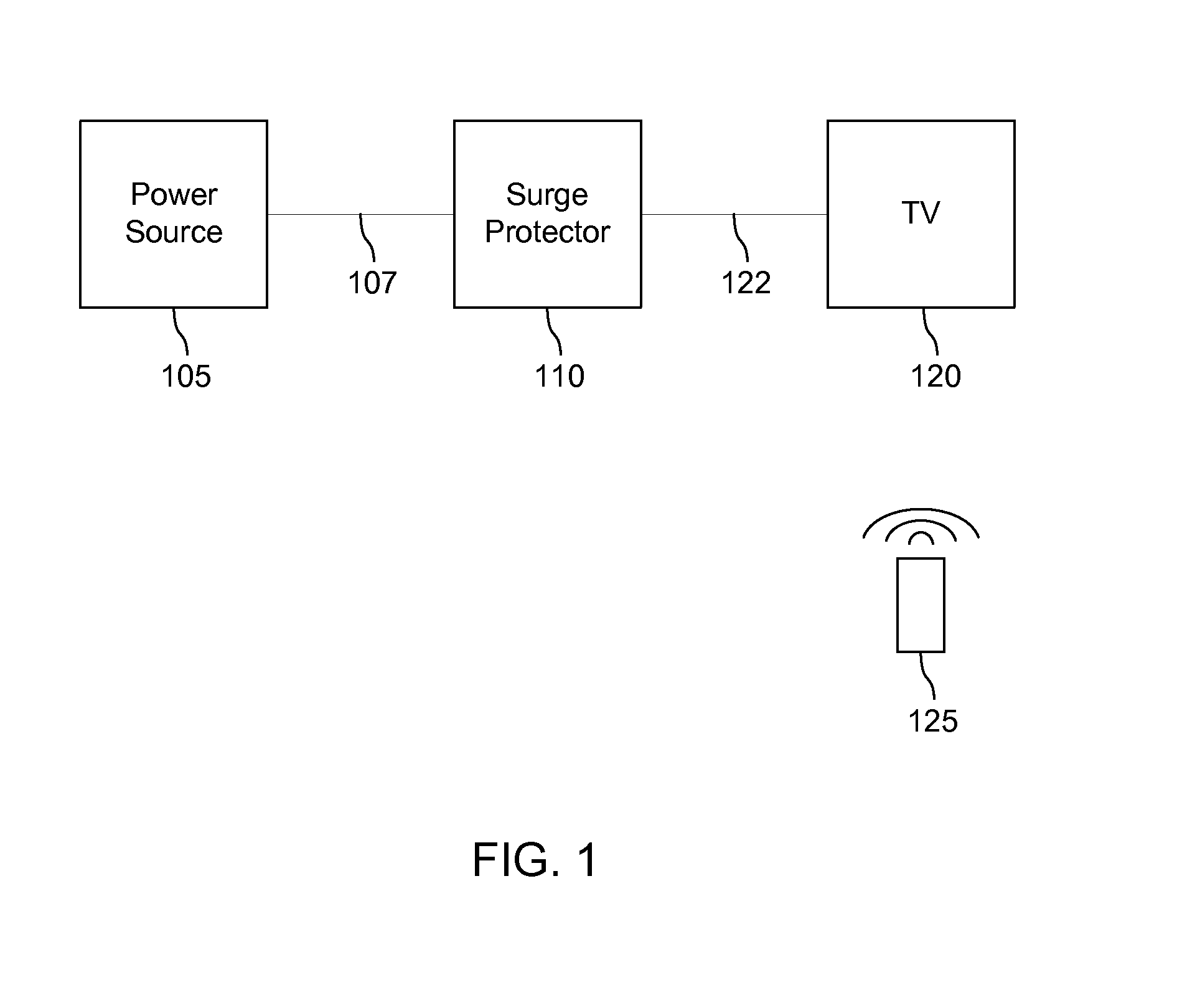
[0030]FIG. 1 is a diagram of a common system for providing power to common household electronic devices. A power source 105 is connected to a surge protector 110 via a power cable 107. Power source 105 is operable to provide alternating current (AC) for the operation of electronic devices. Surge protector 110 is operable to prevent voltage spikes that exceed the operating voltage of an electronic device connected to surge protector 110 which would cause significant damage to an electronic device connected directly to power source 105. Surge protector 110 is connected to a television 120 (herein referred to as TV) via a power cable 122. TV 120 is an electronic device that's primary function is to display video when connected to a video source. A remote 125 is operable to communicate with TV 120 at a distance.

[0031]During normal operation of TV 120 of FIG. 1 a user (not shown) may power TV 120 off by utilizing a power button 125a on remote 125. This method for powering on / off TV 120 d...


PUM


Abstract

A power block is provided having a plurality of individually, remotely controlled power ports switchable between an on state and an off state which users may connect electronic devices. The power block determines the desired power state for the particular power port that a particular electronic device is connected based on infrared codes used to power on or off the particular electronic device and switches the port between the on or off state accordingly.

Description

FIELD OF THE INVENTION[0001]The invention relates in general to a method and apparatus for controlling power supplied to electrical equipment. More particularly the present invention is related to a power control system and method of controlling power to a group of switchable electrical slave outlets to energize and de-energize equipment connected theretoBACKGROUND OF THE INVENTION[0002]It is common for almost every electronic device to be found within three states power consumption. The first state is one in which the device is not connected to a power source. The second state is one in which the device is connected to a power source, yet the electronic device is not powered on. The third state is one in which the device is connected to a power source, and the device is powered on. The difference between states one and two as they relate to power consumption is that in state one the amount of power consumed by the device is zero. In state two a small amount of power is being consum...

Claims


Application Information

Patent Timeline
Patent Type & Authority Applications(United States)
IPC IPC(8): G06F1/32
CPCG08C23/04H04N5/63G08C2201/40G08C2201/10
Inventor CHOMATIL, VIJAYAN
Owner CHOMATIL VIJAYAN
Features
  • R&D
  • Intellectual Property
  • Life Sciences
  • Materials
  • Tech Scout
  • Unparalleled Data Quality
  • Higher Quality Content
  • 60% Fewer Hallucinations
Learn More