Bearing assembly

a technology of bearings and assemblies, applied in the direction of bearings, wing adjustments, aircraft transmission means, etc., can solve the problems of increasing the difficulty of fitting all the necessary systems, affecting the operation of the bearing, and severely limited the size of the actuator that may be used to control the deployment of various control surfaces

Inactive Publication Date: 2012-01-12
AIRBUS OPERATIONS LTD
View PDF2 Cites 5 Cited by
  • Summary
  • Abstract
  • Description
  • Claims
  • Application Information

AI Technical Summary

Benefits of technology

[0025]In one embodiment, the first fixed support member is mountable to an aircraft wing and the second fixed support member is mountable to a control surface.
[0026]In another embodiment, the first fixed support member is mountable to a control surface and the second fixed support member is mountable to an aircraft wing.
[0027]According to another aspect of the invention, there is provided an aircraft wing and a control surface coupled to said wing for deployment during take-off and / or landing, and an actuator system according to the invention extending between and coupled to said control surface and the wing to control deployment of said control surface from said wing.

Problems solved by technology

As demands for thinner, more efficient wing profiles increase, it becomes increasingly difficult to fit all the necessary systems, structure and actuation devices within the wing outer mould line and the size of actuator that may be employed for controlling deployment of various control surfaces is severely limited.
In particular, the length of conventional hydraulic cylinders is a problem, especially as the spherical bearing at each end of the actuator each add between 50 to 200 mm to the length of the actuator which is often unacceptable due to the tight space constraints within the wing structure.
However, as these actuators rely on only one spherical bearing at the moving end of the hydraulic cylinder, the fixed end of the actuator is mounted for movement about one axis, and so they suffer from high wear on the cylinder bushes and seals resulting in premature failure due to hyperstatic loading caused by wing bending and manufacturing tolerances.

Method used


Image

  • Bearing assembly
  • Bearing assembly
  • Bearing assembly

Examples


Embodiment Construction

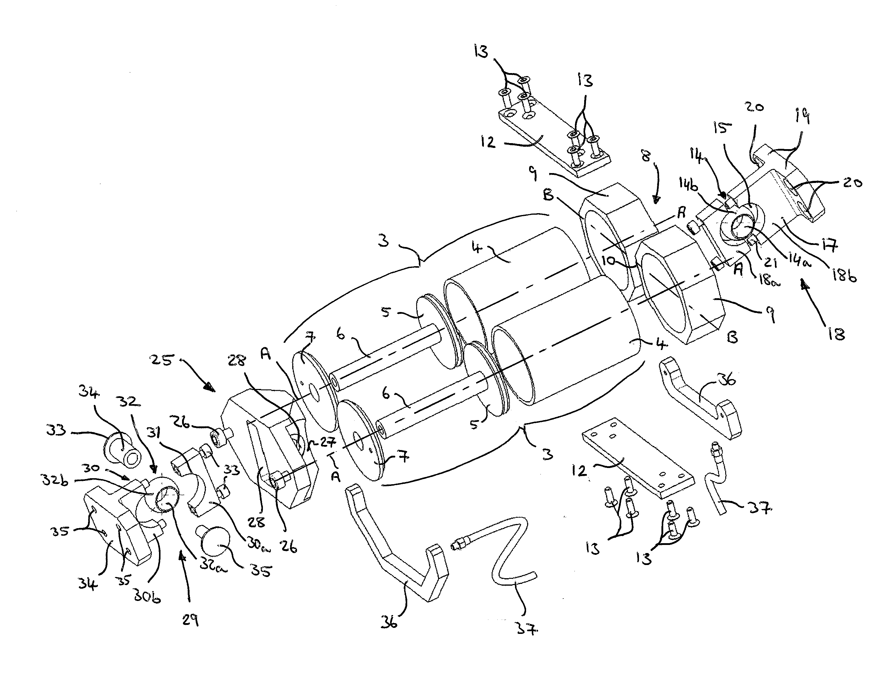
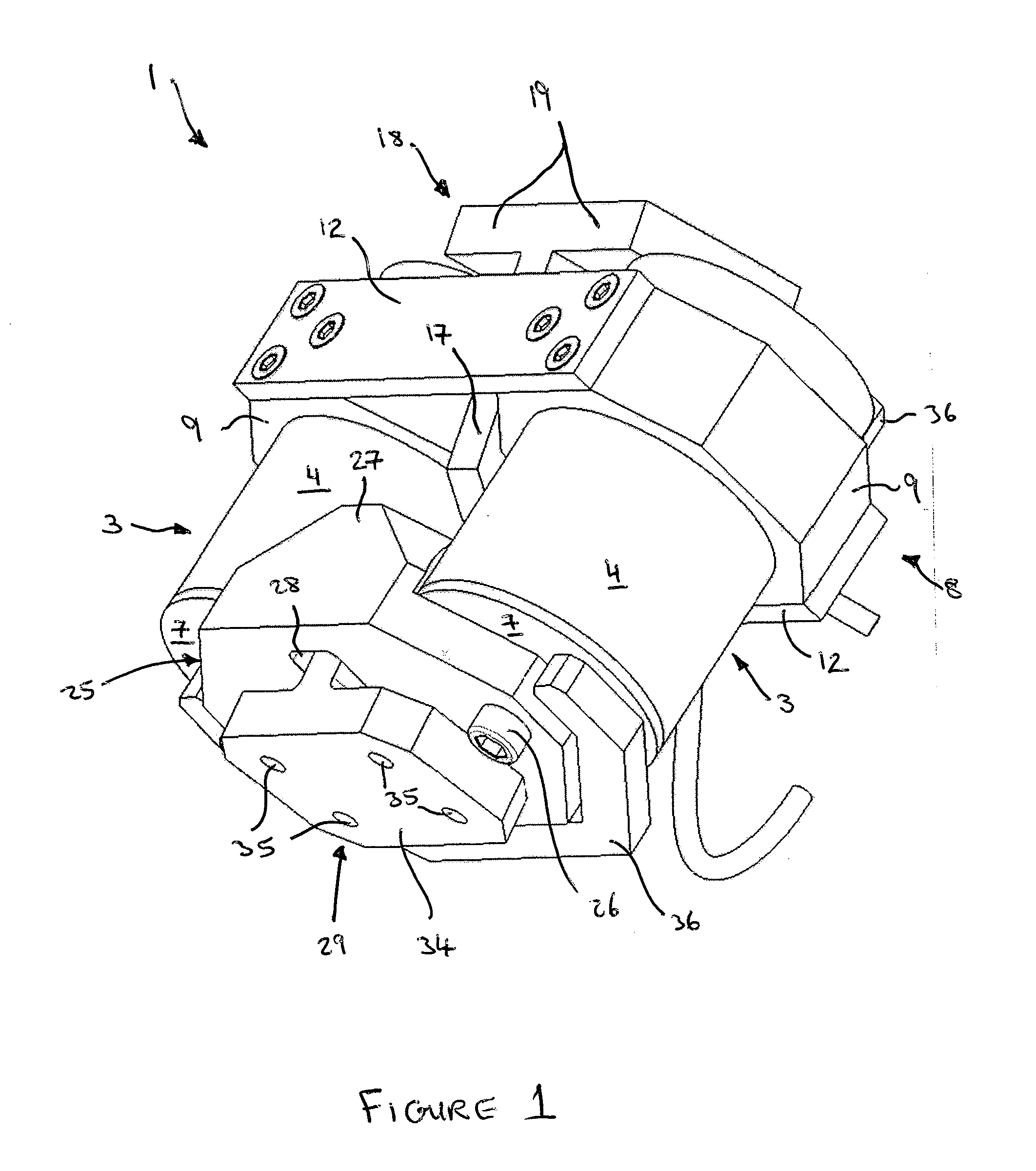
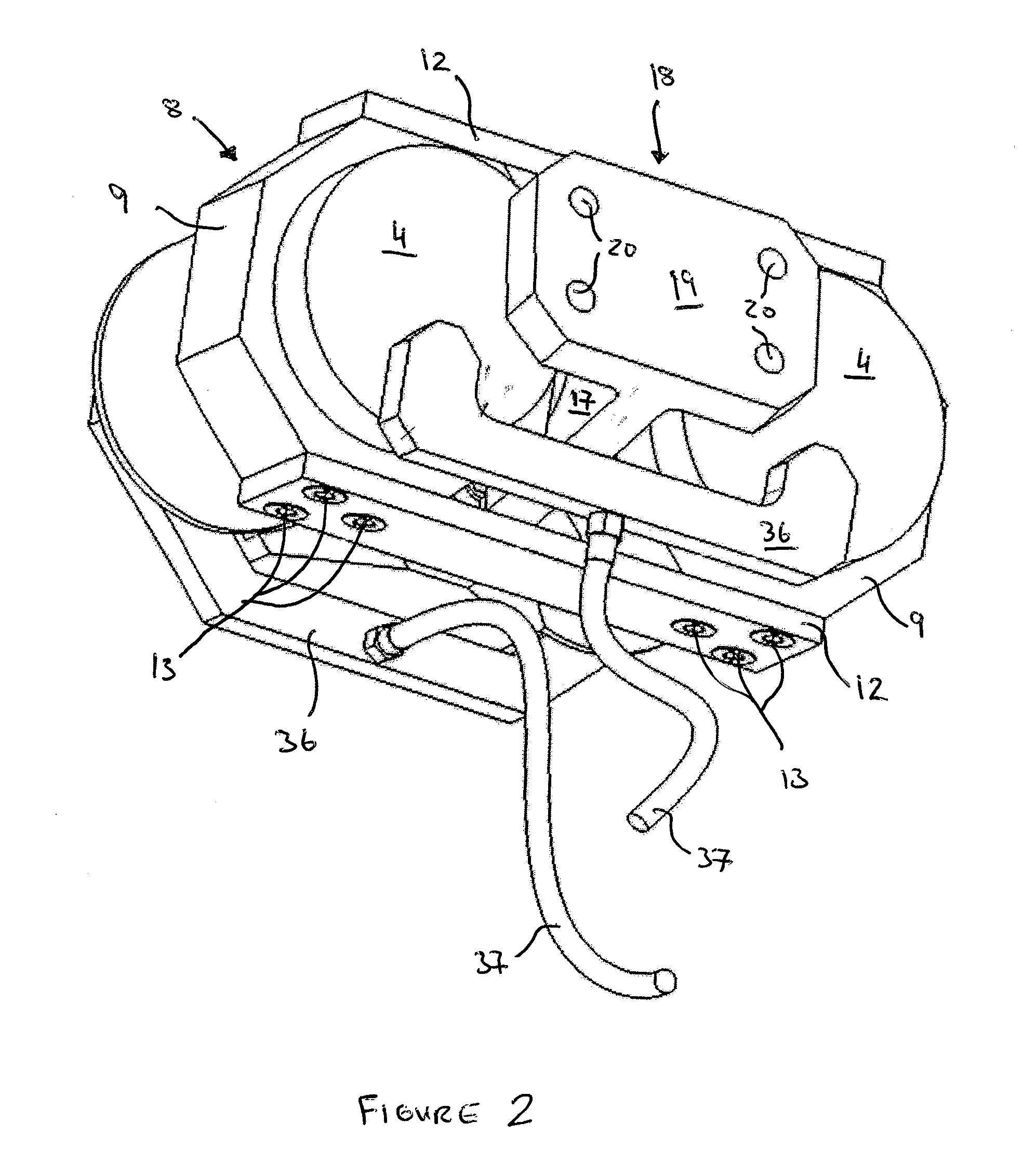
[0033]Referring now to the drawings, there is shown in FIGS. 1 and 2 an actuator system assembly 1 including a bearing assembly according to a preferred embodiment of the invention. The actuator system assembly 1 comprises a pair of spaced hydraulic cylinders 3 whose longitudinal axes (A-A in FIG. 4) are arranged parallel to each other. Each cylinder 3 comprises a cylinder housing 4 with a piston 5 (see FIG. 4) slideably received in the cylinder housing 4 to drive a control surface (not shown) towards and away from an aircraft wing (not shown) as the piston 5 slides into and out of the cylinder housing 4 in response to changes in hydraulic pressure on one side of the piston 5. Each piston 5 has a shaft 6 that extends through a plate 7 closing an end of each cylinder housing 4.

[0034]Referring to the bearing assembly, it comprises a first movable support element 8 having a pair of collars 9 spaced from each other by a shaft 10, which is just visible in FIG. 4 between the collars 9. Th...


PUM


Abstract

A bearing assembly for mounting a pair of spaced parallel actuators (3) between a wing and a control surface of an aircraft so that the actuators control deployment of said control surface from the wing in tandem is disclosed. The bearing assembly comprises a fixed member (18) for attachment to the aircraft and a movable member (8) attachable to the actuators. The fixed and movable members are coupled via a part-spherical bearing (14) and are configured such that the part-spherical bearing is located in the space between the actuators (3).

Description

INTRODUCTION[0001]The present invention relates to a bearing assembly for mounting an actuator to an aircraft wing and to an actuator system assembly comprising the bearing assembly of the invention and the actuators.BACKGROUND[0002]Aircraft need to produce varying levels of lift for take-off, landing and cruise. A combination of wing leading and trailing edge control surfaces are used to control the wing coefficient of lift. The leading edge control surface is known as a slat and a trailing edge control surface is known as a flap. During normal flight the slats and flaps are retracted against the leading and trailing edges of the wing, respectively. However, during take-off and landing they are deployed from the wing so as to vary the airflow across and under the wing surfaces. By varying the extent to which the slats and flaps are deployed from the wing, the lift provided by the wing can be controlled. Other trailing edge control surfaces include ailerons and spoilers.[0003]The co...

Claims


Application Information

Patent Timeline
Patent Type & Authority Applications(United States)
IPC IPC(8): B64C13/42F15B18/00F16C29/04
CPCF15B15/1404B64C13/42
Inventor PARKER, SIMON JOHN
Owner AIRBUS OPERATIONS LTD
Why Eureka
Try Eureka