
Image processing device and image processing method

Active Publication Date: 2012-01-12
SONY COMPUTER ENTERTAINMENT INC
View PDF3 Cites 4 Cited by
  • Summary
  • Abstract
  • Description
  • Claims
  • Application Information

AI Technical Summary

Benefits of technology

[0007]The present invention addresses the issue and a purpose thereof is to provide a technology of reducing user load associated with viewing stereoscopic images.

Problems solved by technology

If the images displayed on the display device are not suitable as stereoscopic images, the user may experience heavy load associated with adjustment.
Considering the fact that imaging devices capable of generating stereoscopic images are becoming available to users not experienced with capturing stereoscopic images, images not suitable as stereoscopic images may be generated in an increasing number of cases.

Method used


Image

  • Image processing device and image processing method
  • Image processing device and image processing method
  • Image processing device and image processing method

Examples


Embodiment Construction

[0026]The invention will now be described by reference to the preferred embodiments. This does not intend to limit the scope of the present invention, but to exemplify the invention.

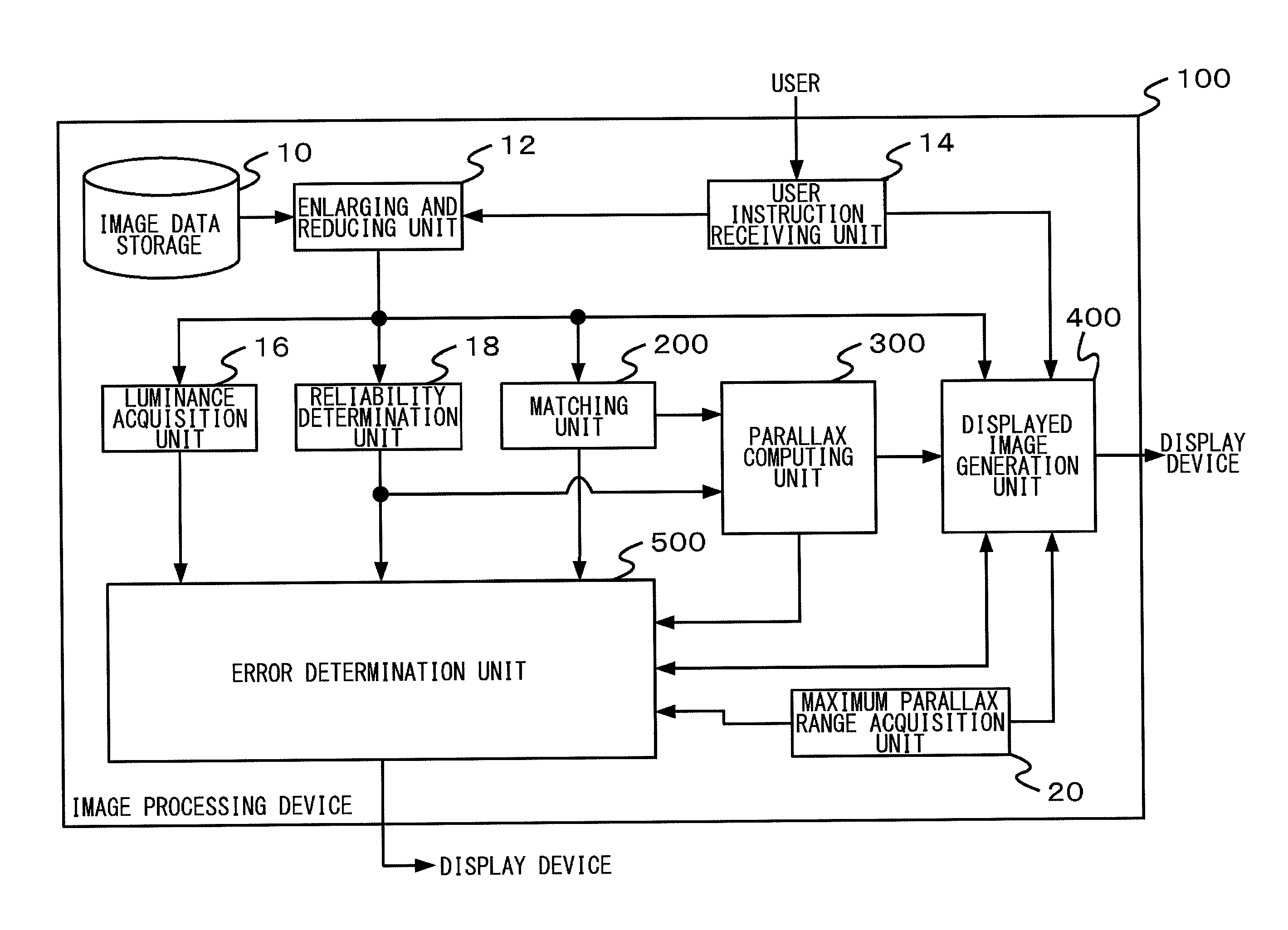
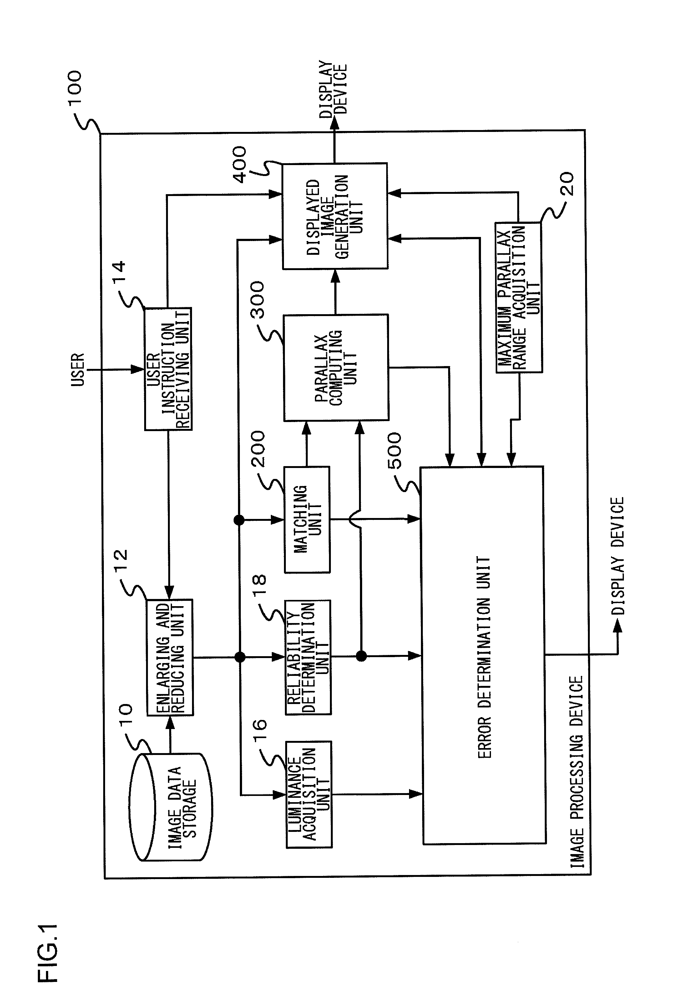
[0027]A summary of the embodiment will be described. Prior to displaying stereoscopic images on a display device, an image processing device 100 according to the embodiment examines the distribution of parallax in a parallax image for the left eye and a parallax image for the right eye included in the stereoscopic images. The device 100 examines whether the images are suitable as stereoscopic images and displays the result on the display device.

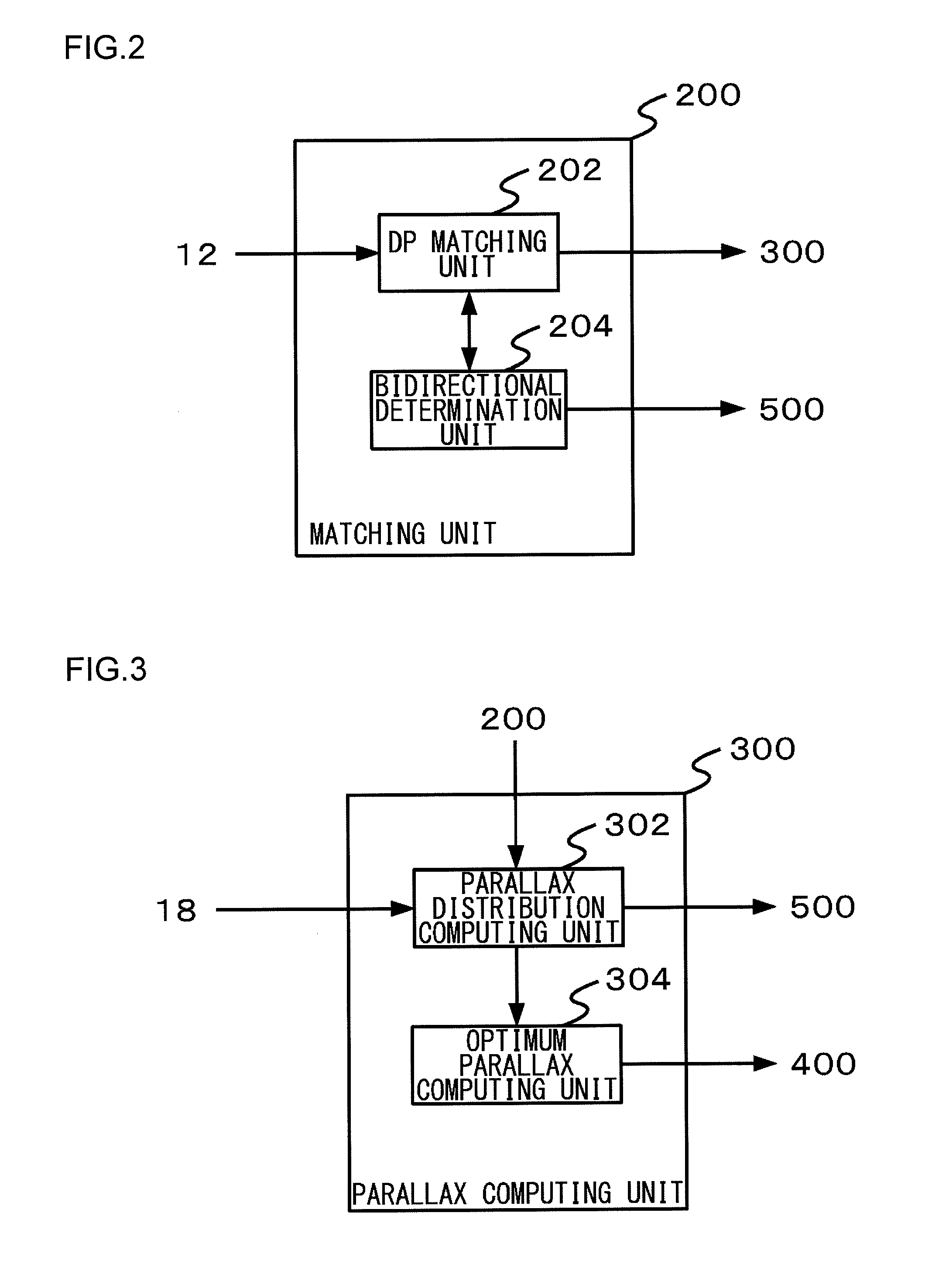
[0028]FIG. 1 schematically shows the internal configuration of the image processing device 100 according to the embodiment. The image processing device 100 according to the embodiment comprises an image data storage 10, an enlarging and reducing unit 12, a user request receiving unit 14, a luminance acquisition unit 16, a reliability determination unit 18, a maxim...


PUM


Abstract

A location error determination unit determines, prior to displaying on a display device stereoscopic images including a parallax image for the left eye and a parallax image for the right eye of a subject, whether the parallax image for the left eye and the parallax image for the right eye are stereoscopic images that can be located as three-dimensional images. A parallax error determination unit determines, when it is determined that the parallax image for the left eye and the parallax image for the right eye can be located as stereoscopic images, whether a range of distribution of parallax between the parallax image for the left eye and the parallax image for the right eye is accommodated within a predetermined parallax range. An error communicating unit communicates an error when it is determined that that the parallax image for the left eye and the parallax image for the right eye cannot be located as stereoscopic images or when it is determined that the range of parallax between the parallax image for the left eye and the parallax image for the right eye is not accommodated within the predetermined parallax range.

Description

BACKGROUND OF THE INVENTION[0001]1. Field of the Invention[0002]The present invention relates to image processing devices and image processing methods.[0003]2. Description of the Related Art[0004]Imaging devices capable of generating stereoscopic images including a parallax image for the left eye and a parallax image for the right eye of a subject are becoming available to the public. Imaging devices like this may be implemented by, for example, multi-lens cameras having two or more optical systems for imaging. Alternatively, parallax images may be generated by subjecting an image captured from a plurality of viewpoints using a single-lens camera to image processing.[0005]Meanwhile, display devices capable of presenting images with depth to a user by presenting a parallax image for the left eye included in stereoscopic images to the user's left eye and presenting a parallax image for the right eye to the user's right eye are becoming available to the public. In particular, consumer ...

Claims


Application Information

Patent Timeline
IPC IPC(8): H04N13/04
CPCH04N13/0022G06T7/0022H04N13/0497G06T7/97H04N13/128H04N13/398
Inventor MORISADA, HIDEHIKOSHINOHARA, TAKAYUKIOHKUBO, HIROMASA
Owner SONY COMPUTER ENTERTAINMENT INC
Learn More