Systems, methods, and apparatus for connection fault self-monitoring with DC bias current

a technology of dc bias current and self-monitoring, which is applied in the direction of fault location, line-transmission details, instruments, etc., can solve the problems of difficult diagnosis and correction, unsafe conditions

Active Publication Date: 2012-01-19
GENERAL ELECTRIC CO
View PDF0 Cites 9 Cited by
  • Summary
  • Abstract
  • Description
  • Claims
  • Application Information

AI Technical Summary

Problems solved by technology

When a connector fails or when a cable develops an open conductor condition, erroneous signals may go un-noticed and may lead to unsafe conditions, for example, or the machinery being monitored may operate incorrectly until operators notice the problem and repair the connection.
In such scenarios, the received excitation signal can appear to be a valid signal, and may be extremely difficult to diagnose and correct.

Method used


Image

  • Systems, methods, and apparatus for connection fault self-monitoring with DC bias current
  • Systems, methods, and apparatus for connection fault self-monitoring with DC bias current
  • Systems, methods, and apparatus for connection fault self-monitoring with DC bias current

Examples


Embodiment Construction

[0013]Embodiments of the invention will be described more fully hereinafter with reference to the accompanying drawings, in which embodiments of the invention are shown. This invention may, however, be embodied in many different forms and should not be construed as limited to the embodiments set forth herein; rather, these embodiments are provided so that this disclosure will be thorough and complete, and will fully convey the scope of the invention to those skilled in the art. Like numbers refer to like elements throughout.

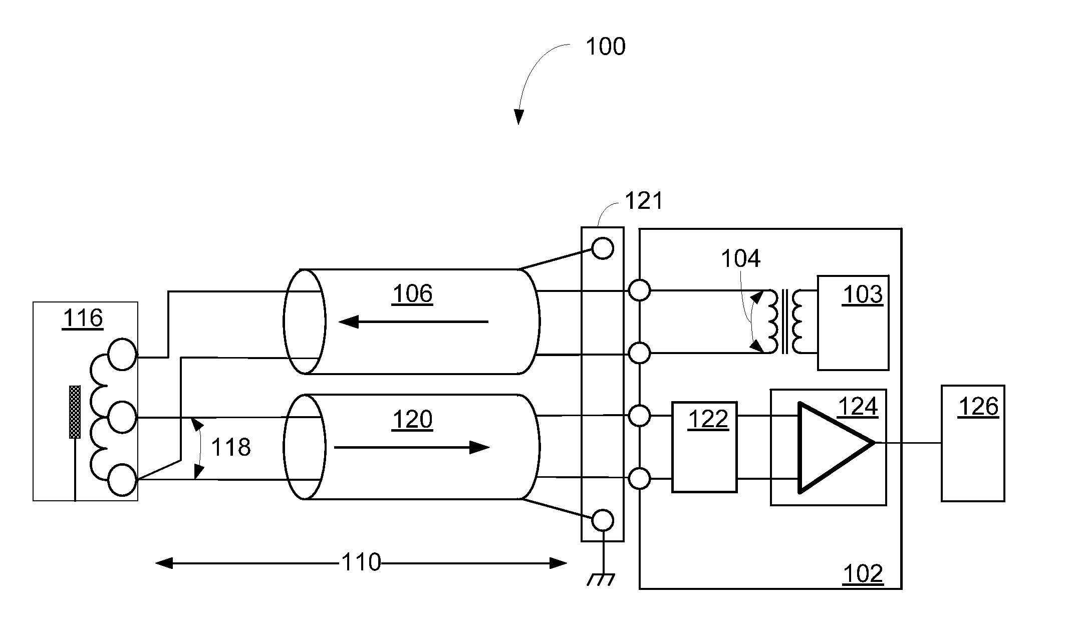
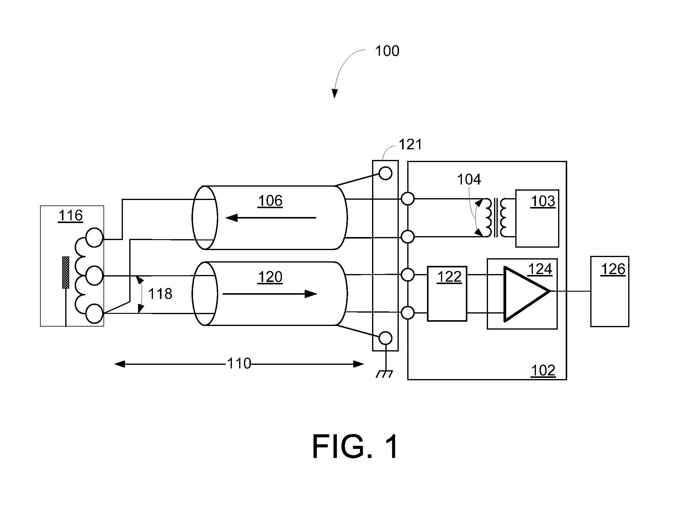
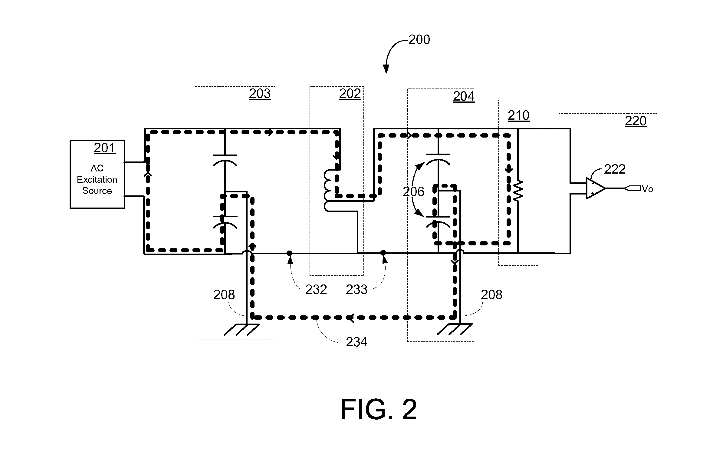
[0014]Certain embodiments of the invention may enable self-monitoring of circuit connectivity issues associated with a sensor system. According to certain example embodiments, a small bias current may be injected into the circuit path of a voltage mode sensor such that the bias current flows through all of the series connections, cables and sensor. Due to a small resistance of the voltage mode sensor, the bias current may produce a small voltage drop across the s...


PUM


Abstract

Certain embodiments of the invention may include systems, methods, and apparatus for providing connection fault self-monitoring with DC bias current. According to an example embodiment of the invention, a method is provided for obtaining measurements and detecting connectivity faults associated with a voltage mode sensor. The method can include coupling a DC bias current into a circuit. The circuit includes a voltage mode sensor, and the voltage mode sensor can output a time varying signal. The method can also include setting a nominal level of the DC bias current, monitoring a voltage associated with the DC bias current, and determining circuit connectivity status based at least in part on monitoring the voltage.

Description

FIELD OF THE INVENTION[0001]This invention generally relates to connection fault monitoring, and in particular, to connection fault self-monitoring with a DC current.BACKGROUND OF THE INVENTION[0002]Sensor systems often require multiple connectors and long cable runs to transmit signals from the sensor elements to receivers and processors located remotely. When a connector fails or when a cable develops an open conductor condition, erroneous signals may go un-noticed and may lead to unsafe conditions, for example, or the machinery being monitored may operate incorrectly until operators notice the problem and repair the connection. In certain sensors, particularly in linear variable differential transformer (LVDT)-based sensors, remotely generated excitation signals can be provided to sensor elements by shielded twisted pair excitation cables, for example. The amplitude of the excitation signal coupling through the LVDT sensor as a function of the sensor position, for example, may th...

Claims


Application Information

Patent Timeline
Patent Type & Authority Applications(United States)
IPC IPC(8): G01R31/04
CPCG01D3/08G01R31/2829G01R31/08G01R31/026G01R31/54
Inventor CARTER, ROY ANTHONYBRACKMAN, JR., WILLIAM DUGGANBOOTH, JOHN ROBERT
Owner GENERAL ELECTRIC CO
Why Eureka
Try Eureka