Compact multibeam reflector antenna

a multi-beam, reflector technology, applied in the direction of antennas, waveguide horns, electrical devices, etc., can solve the problems of excessive light blockage, distorting the architectural image of buildings, and installation of parabolic antennas on building walls

Inactive Publication Date: 2012-01-19
TELEFRONTIER
View PDF4 Cites 45 Cited by
  • Summary
  • Abstract
  • Description
  • Claims
  • Application Information

AI Technical Summary

Benefits of technology

[0022]The objective of this invention is to provide a compact (i.e., with a minimum ratio between

Problems solved by technology

When those antennas are installed outdoor, they distort the architectural image of buildings.
In particular, some countries of the European Union adopted legislation limiting installation of parabolic antennas on building walls and roofs.
When fixed near balconies or windows, antennas lead to excessive light blockage.
One limitation of the above single reflector and dual-reflector antennas with one feed, which are designed for

Method used


Image

  • Compact multibeam reflector antenna
  • Compact multibeam reflector antenna
  • Compact multibeam reflector antenna

Examples


Embodiment Construction

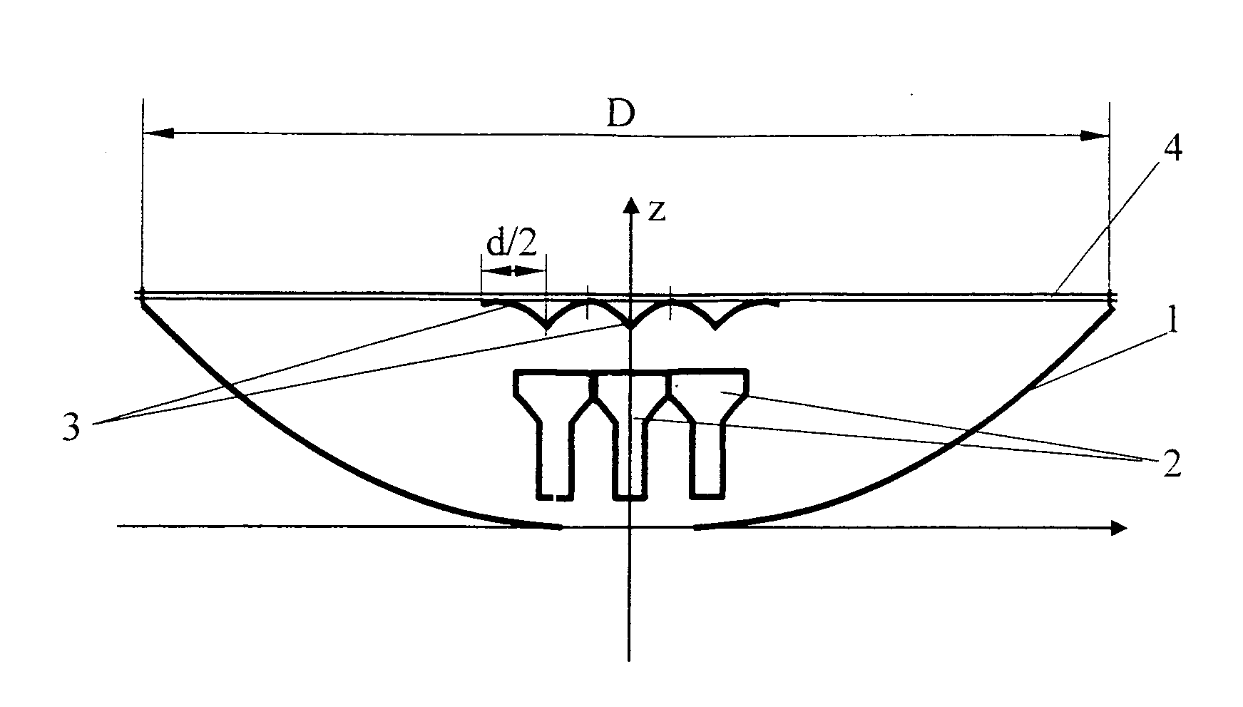
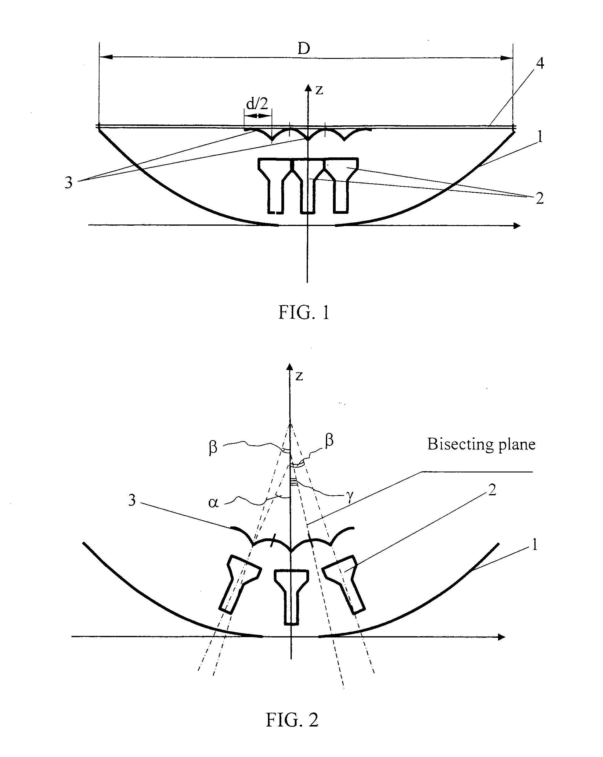
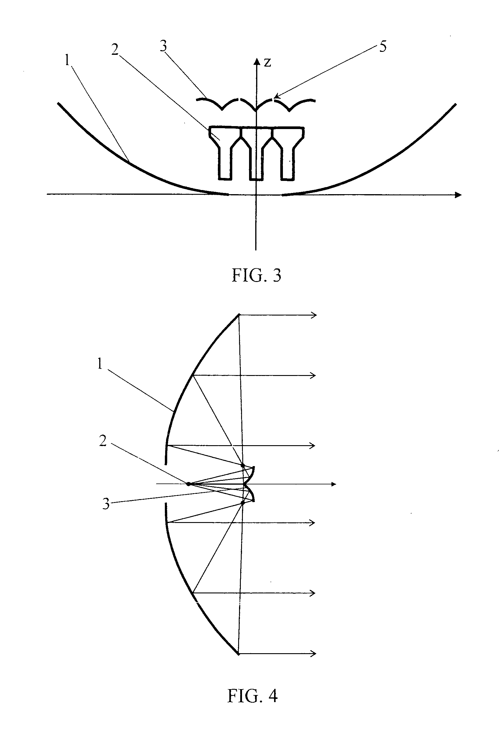
[0056]The antenna shown in FIG. 1-3 comprises a main reflector 1, at least two feeds 2 and at least two sub-reflectors 3. Each of the sub-reflectors 3 is designed for re-reflecting a wave from its corresponding feed 2 to the main reflector 1 and converting a wave front from a feed 2 into a plane front (FIG. 4) of a wave reflected from the main reflector 1. The main reflector 1 is made as a body of revolution, mainly with a parabolic generatrix.

[0057]Each sub-reflector 3 is made with an external surface form which ensures reflection of the directional pattern central beam from a feed 2 to lateral parts of the main reflector 1 and reflection of a lateral beam to the central area of the main reflector 1. The adjoining surfaces of the sub-reflectors 3 are truncated.

[0058]A common cover 4 may be added to the device by installing it on the plane of the edge of the main reflector 1 and fixing the sub-reflectors 3 on the cover 4 (FIG. 1).

[0059]The feeds 2 may be made, in particular, as horn...


PUM


Abstract

The inventive device enables to ensure its compactness, that is, a minimum thickness at a high antenna efficiency of an antenna in the frequency range 10.7-12.75 GHz. This technical effect can be achieved because the antenna comprises a main reflector (1), at least two feeds (2) and at least two sub-reflectors (3). Each sub-reflector is provided with such a shape of its external surface that ensures reflection of the feed directional pattern central beam to the edge of the main reflector and reflection of a lateral beam to the central area of the main reflector, the sub-reflector adjoining surfaces being truncated.

Description

TECHNICAL FIELD[0001]This invention relates to antenna and feeder devices and may be used as a satellite television antenna.BACKGROUND ART[0002]Parabolic reflector antennas are widely used as satellite television antennas owing to a number of factors, including:[0003]low cost;[0004]wide band of operating frequencies;[0005]simple work with waves of different polarizations;[0006]relatively high aperture efficiency (AE) (usually 60-65 per cent).[0007]A parabolic antenna comprises a main reflector of which the surface is the result of parabolic movement along a trajectory in 3D space. The most common type of such reflector is the result of parabolic generatrix rotation around the axis passing through the parabola apex and focus. The parabolic antenna feed is located in the parabola focus. Thus a directional pattern with one main maximum (beam) is formed in the direction of the parabola axis. The shortcomings of parabolic antennas of this type are the characteristics of its single-beam a...

Claims


Application Information

Patent Timeline
IPC IPC(8): H01Q19/19H01Q13/02
CPCH01Q25/007H01Q19/19H01Q15/14H01Q19/17
Inventor AHN, JIHOVENETSKIY, ALEXANDERFROLOVA, ELENA
Owner TELEFRONTIER
Why Eureka
Try Eureka