
Montana long ranger rifle rest

a long ranger and rest technology, applied in the field of foldable rests, can solve the problems of reducing the range of action, and reducing the accuracy of firm rests, so as to enhance the rigidity of the target pivot tube attachment accessories and reduce the bulk

Inactive Publication Date: 2012-01-26
KERN DARRIN LEE
View PDF0 Cites 11 Cited by
  • Summary
  • Abstract
  • Description
  • Claims
  • Application Information

AI Technical Summary

Benefits of technology

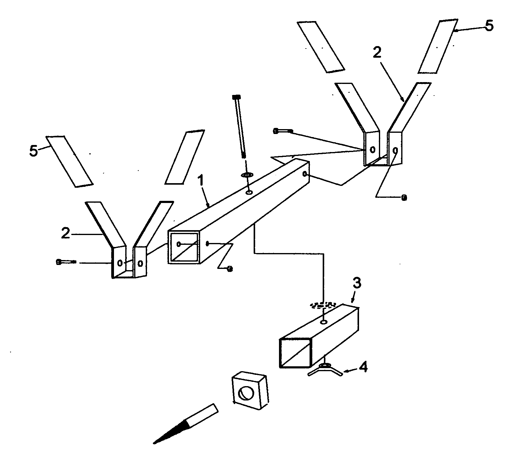
[0006]The present invention provides a foldable, lightweight portable, in- the- field rifle rest for accurate hunting and target shooting, with an attachment fixture to photograph or video record the shot or the hunt. The rest has folding capabilities to minimize bulk when carried into the field on a person. It is opened by pivoting the screw outward and firming its position with the adjustment wing handle. The firm attaching method incorporated in the rest includes a screw for fastening the rest to objects including but not limited to a tree, bush, or other penetrable surface. Available accessories include a target pivot tube arm that replaces the screw arm, a ratchet strap arm that replaces the screw arm, a clamp arm that also replaces the screw arm and an optional anchor arm that enhances further rigidity to the target pivot tube attachment accessory. The screw would be turned into a penetrable surface such as but not limited to a tree or bush.
[0007]To secure the rest with the target attachment accessory put in place, the aim of the rifle, horizontal as well as vertical is quickly locked into place with the adjustment wing handle. With the rachet strap attachment accessory put in place on the rest, rachet straps can be put around objects including but not limited to trees, fence posts, or other objects that they may fit around. With the clamp attachment accessory put in place on the rest, the clamp can be closed on objects including but not limited to trucks, cars, ATV's, fences, etc. A camera bracket attached to the rest allows either a spotting scope or a video camera to be attached to the rest. Once the rest is secured as mentioned in the preceding attachment methods, the two rifle support prongs are pivoted out of their folded positions in preparation to receive the rifle. The rifle is placed on the rest into and between the two rifle support prongs in the front and back of the rest. Because of the universal flexibility of the screw and other accessory mounting shaft methods, on either side of the rifle support beam, the front and back for the rest is determined by the mounting position or if the user is left or right handed. The prongs are tapered to allow different sized rifles by their placement depth into and between the prongs. The prongs are coated with rubber to protect the rifle finish and more securely hold the rifle in a fixed position. With the rifle in a two point secured position it is now rigid for aiming. By loosening or tightening the adjustment wing handle located under the screw arm, the shooter can reposition the rifle's left to right aim as needed and re- secure it as needed.
[0009]The camera / spotting scope bracket is removed from the rifle support beam by turning and withdrawing the camera mounting screw holding the camera / spotting scope to the side of the rifle support beam. Once loose, the camera / spotting scope bracket can be withdrawn from its holstered position. The camera / spotting scope bracket is put into position by threading it on the left or right side of the rifle support beam depending on desired mounting position. The camera or spotting scope can now be attached to the rest with the screw common to the adapting methods of most cameras and spotting scopes. Once the camera or spotting scope is put into position corresponding to the aimed rifle, it can visually capture the object being shot at by the rifle no matter where the rifle is aimed while fixed on the rest.

Problems solved by technology

They consist of less portable heavier rests not suitable for field use and portability.
Again, this rest does not offer any adjustment or portability, requiring a tree stand or platform for attachment.
Some rifle rests only allow the front portion or forearm portion of the rifle to rest, restricting the firm rest accuracy.

Method used


Image

  • Montana long ranger rifle rest
  • Montana long ranger rifle rest
  • Montana long ranger rifle rest

Examples


Embodiment Construction

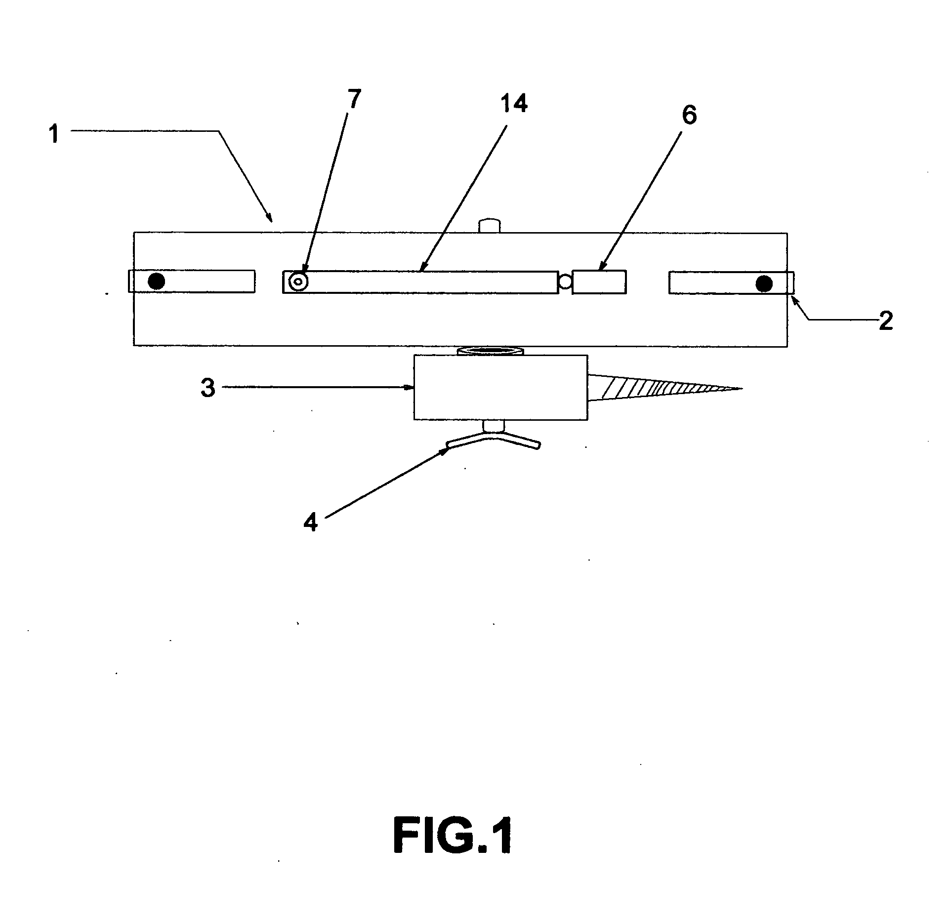
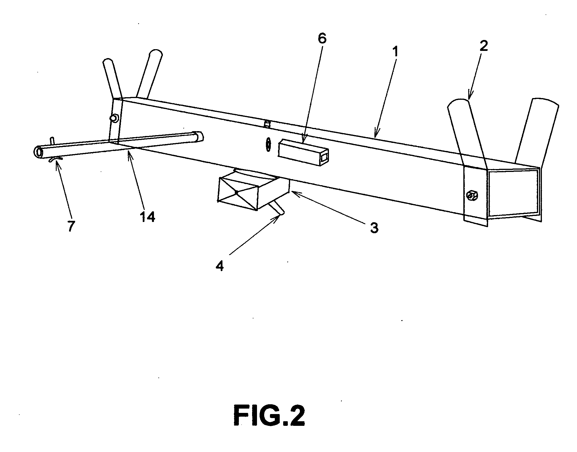
[0021]Referring to the drawings throughout several views corresponding to like elements, FIG. 1 indicates the folded rest in a position to be easily carried on a person. FIG. 2 indicates the rest in an open position whereby the screw arm is loosened from the rifle support beam by turning the adjustment wing handle, permitting the screw arm to be turned either left or right, positioning the screw arm for tree attachment. When the appropriate position of the arm is made, the adjustment wing handle is tightened. FIG. 2 indicates the screw arm in a right angle position to the rifle support beam whereby the entire rest can be used to turn the screw into a tree. FIG. 3, refers to the rest in the attached position to a tree utilizing the screw arm attachment accessory. FIG. 2 indicates the front and rear rifle support prongs pivoted upwards from the folded position to receive the rifle. FIG. 3A indicates the camera / spotting scope bracket attached to the rifle support beam after it is remov...


PUM


Abstract

A folding, compact, lightweight, in-the-field Hunting and Target Rifle Rest is disclosed utilizing a novel solid means of attachment to hold a rifle securely in place for maximum accuracy. The rest includes various means of attachments to solid objects including but not limited to trees, stumps, shrubs, tripods, or any other objects that may be strapped to or clamped to and fit into the rest clamp. The rest incorporates various means of adjusting the rifle when secured for repositioning its aim and comfort to the user. The rest includes attachment hardware for cameras and spotting scopes that can directly focus at the same time, on the same field of view, that the rifle is aimed towards no matter how the rifle's aim is repositioned.

Description

CROSS-REFERENCE TO RELATED APPLICATIONS[0001]I claim the benefit of the filing date of provisional application and the date it was filed 61 / 279,609 Oct. 23, 2009STATEMENT REGARDING FEDERALLY SPONSORED RESEARCH OR DEVELOPMENT[0002]N / AREFERENCE TO SEQUENCE LISTING, A TABLE, OR A COMPUTER PROGRAM LISTING COMPACT DISC APPENDIX[0003]N / ABACKGROUND OF THE INVENTION[0004]The present invention relates to an improved foldable compact method to hold and secure a hunting or target rifle in a field-use situation.[0005]Known methods for securing rifles in target and hunting situations require secure table top type platforms to hold these rests. Examples of these are shown in U.S. Pat. Nos. D540, 9045s; and D471, 248S. They consist of less portable heavier rests not suitable for field use and portability. A tree hook rests in U.S. Pat. No. Des 348,215s offers only a single non-adjustable rest which is also referred to as a tree attachment. Another example of a rifle rest is covered in U.S. Pat. No...

Claims


Application Information

Patent Timeline
Patent Type & Authority Applications(United States)
IPC IPC(8): F41A23/02
CPCF41A23/16
Inventor KERN, DARRIN LEE
Owner KERN DARRIN LEE
Learn More