Method of minimizing the attitude hump phenomenon and a rotary wing aircraft provided with stabilizer means therefor

a technology of rotary wing aircraft and stabilizer means, which is applied in the direction of aircraft, aircraft components, rotorcraft, etc., can solve the problems of increasing being remote from and being unable to use pitching stabilizers, etc., to achieve the effect of minimizing the attitude hump phenomenon

Active Publication Date: 2012-01-26
EUROCOPTER
View PDF2 Cites 13 Cited by
  • Summary
  • Abstract
  • Description
  • Claims
  • Application Information

AI Technical Summary

Benefits of technology

[0025]An object of the present invention is thus to propose a method and a device enabling the attitude hump phenomenon to be minimized in a rotary wing aircraft having pitching-stabilizer members that are likely to be impacted by an air stream coming from said rotary wing.

Problems solved by technology

However, on a traditional helicopter flying in translation at low speed or even hovering, the air that passes through the main rotor is deflected rearwards and impacts against the pitching-stabilizer means.
Under such circumstances, it would appear to be impossible to use pitching-stabilizer means having a large wing area on a helicopter, without that giving rise to an increase in the attitude hump phenomenon.
Those documents provide teaching that is of interest, but it nevertheless remains remote from minimizing the attitude hump phenomenon.

Method used


Image

  • Method of minimizing the attitude hump phenomenon and a rotary wing aircraft provided with stabilizer means therefor
  • Method of minimizing the attitude hump phenomenon and a rotary wing aircraft provided with stabilizer means therefor
  • Method of minimizing the attitude hump phenomenon and a rotary wing aircraft provided with stabilizer means therefor

Examples


first embodiment

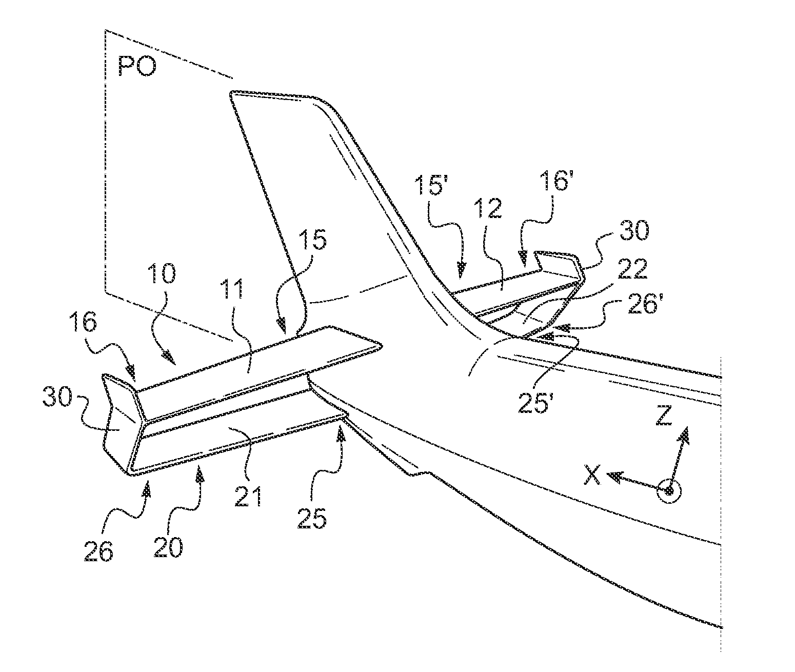
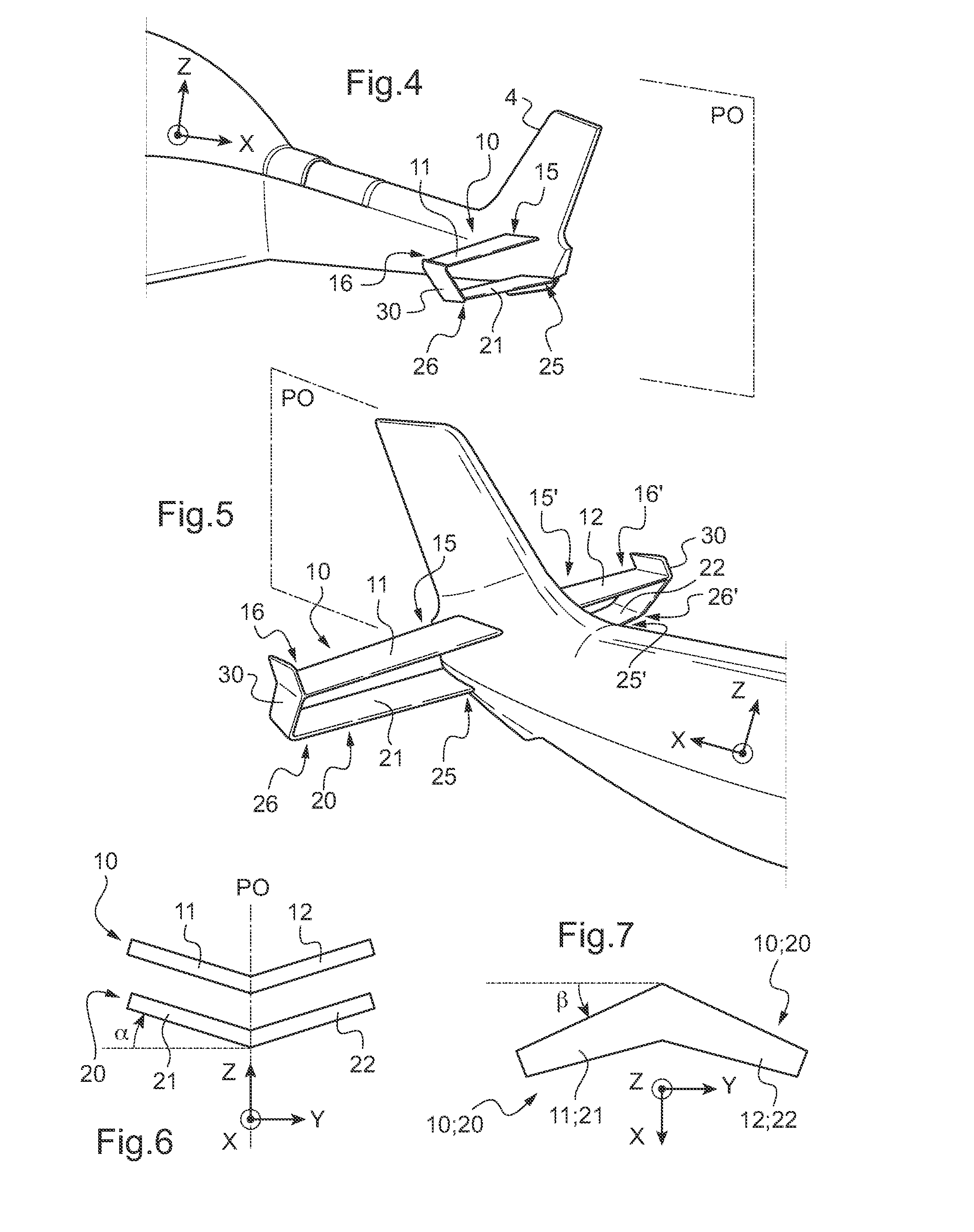
[0079]In FIG. 4, the upper stabilizer means 10 has a single upper stabilizer surface 11 extending from a fixed end 15 secured to the airframe 2 towards a free end 16.

[0080]Likewise, a lower stabilizer means 20 comprises a single lower stabilizer surface 21 extending from a fixed end 25 secured to the airframe 2 towards a free end 26.

[0081]The free end 16 of the upper stabilizer surface may be connected to the free end 26 of the lower stabilizer surface 21 by a more or less vertical airfoil 30, such as a side plate, for example.

second embodiment

[0082]In FIG. 5, the upper stabilizer means 10 has a first upper stabilizer surface extending in a first direction from a fixed end 15 secured to the airframe 2 to a free end 16, and a second upper stabilizer surface 12 extending in a second direction opposite from the first direction from a fixed end 15′ secured to the airframe 2 towards a free end 16′.

[0083]The first upper stabilizer surface 11 and the second upper stabilizer surface 12 may be symmetrical about the antero-posterior plane P0.

[0084]Likewise, the lower stabilizer means 20 comprise a first lower stabilizer surface 21 extending in a first direction from a fixed end 25 secured to the airframe 2 towards a free end 26 and a second lower stabilizer surface 22 extending in an opposite second direction from a fixed end 25′ secured to the airframe 2 towards a free end 26′.

[0085]The lower upper stabilizer surface 21 and the second lower stabilizer surface 22 may be symmetrical about the antero-posterior plane P0.

[0086]It can b...


PUM


Abstract

A method of minimizing the attitude hump phenomenon relating to a rotary wing aircraft (1) having an airframe (2) extending longitudinally from a front end (3) to a rear end (4) together with upper pitching-stabilizer means (10) and at least one lower pitching-stabilizer means (20). Under such circumstances, each lower stabilizer means (20) is placed in a wake (8) from said upper stabilizer means (10) as generated by a stream of air (7) passing through said rotary wing (5) and impacting against the upper surface (10′) of an upper stabilizer means (10).

Description

CROSS REFERENCE TO RELATED APPLICATIONS[0001]This application claims the benefit of FR 10 03035 filed on Jul. 20, 2010, the disclosure of which is incorporated in its entirety by reference herein.BACKGROUND OF THE INVENTION[0002](1) Field of the Invention[0003]The present invention relates to a method of minimizing the attitude hump phenomenon and to a rotary wing aircraft provided with means for performing the method and in particular a helicopter.[0004](2) Description of Related Art[0005]Conventionally, a helicopter comprises an airframe extending longitudinally from a front end to a rear end on either side of an antero-posterior plane of symmetry, and in a vertical direction from a bottom portion fitted with landing gear towards a top portion fitted with a main lift and propulsion rotor.[0006]Furthermore, the airframe has a tail rotor at its rear end. The tail rotor serves to counter the torque exerted by the main rotor on the airframe, and it also enables the pilot to control ya...

Claims


Application Information

Patent Timeline
Patent Type & Authority Applications(United States)
IPC IPC(8): B64C27/04
CPCB64C2027/8281B64C27/82
Inventor BORIE, SYLVIELEYDER, SAMUELALLONGUE, MARC
Owner EUROCOPTER
Why Eureka
Try Eureka