Rotor drive and control system for a high speed rotary wing aircraft

a rotary wing aircraft and control system technology, applied in the field of rotary wing aircraft, can solve the problems of slow airflow velocity across the retreating blade, the tendency of the retreating blade to stall at high forward airspeed, and the limitation of the forward airspeed of the conventional rotary wing aircraft, so as to minimize the major source of vibration

Active Publication Date: 2006-11-30
SIKORSKY AIRCRAFT CORP
View PDF14 Cites 72 Cited by
  • Summary
  • Abstract
  • Description
  • Claims
  • Application Information

AI Technical Summary

Benefits of technology

[0013] The present invention therefore provides a rotor drive and control system for a high spe

Problems solved by technology

The forward airspeed of a conventional rotary wing aircraft is limited by a number of factors.
Among these is the tendency of the retreating blade to stall at high forward airspeeds.
As the forward airspeed increases, the airflow velocity across the retreating blade slows such that the blade may approach a stall condition.
This dissymmetry may create an unstable condition if lift is not equalized across the advancing and retreating sectors of the rotor disc.
However, as the forward airspeed is increased beyond a given point for a given rotor rpm, the flapping and feathering action eventually becomes inadequate to mai

Method used


Image

  • Rotor drive and control system for a high speed rotary wing aircraft
  • Rotor drive and control system for a high speed rotary wing aircraft
  • Rotor drive and control system for a high speed rotary wing aircraft

Examples


Embodiment Construction

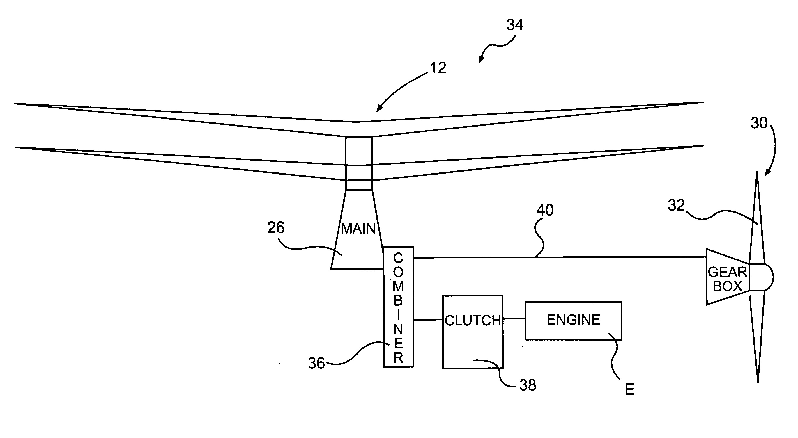
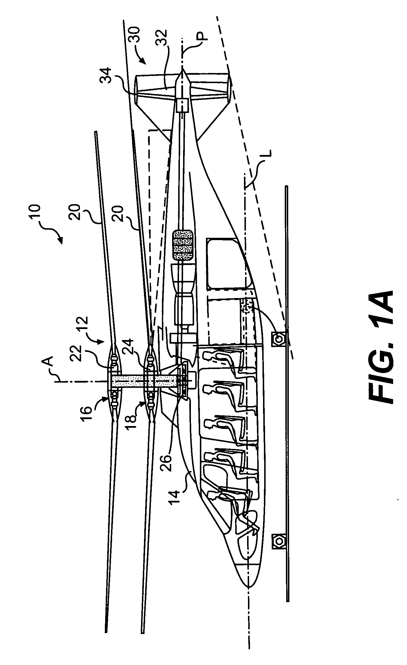
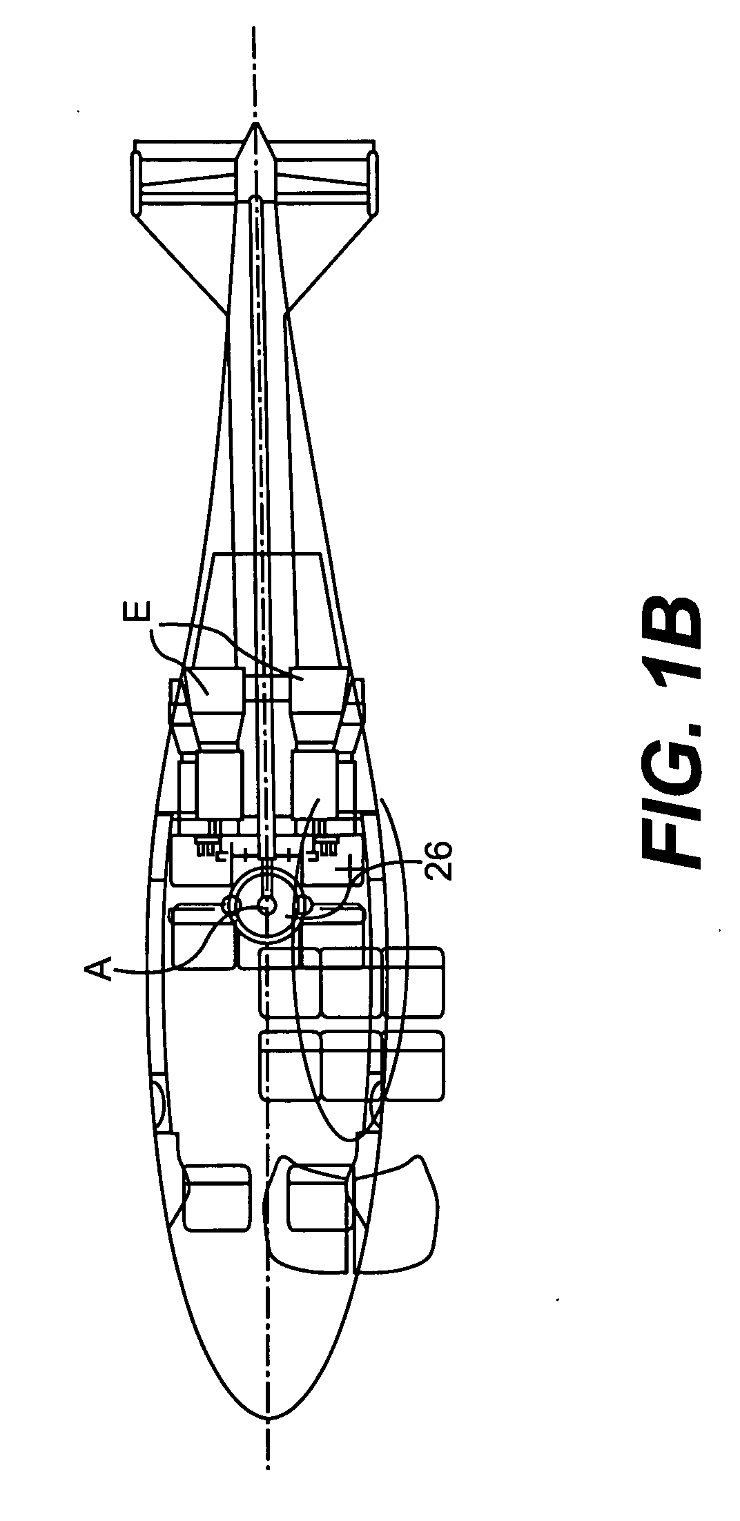
[0019]FIG. 1A-1B illustrates a vertical takeoff and landing (VTOL) high speed compound or coaxial contra-rotating rigid rotor aircraft (collectively rotary-wing aircraft) 10 having a dual, contra-rotating, coaxial main rotor system 12, which rotates about a rotor axis of rotation A. The aircraft 10 includes an airframe 14 which supports the dual, contra-rotating, coaxial main rotor system 12 as well as a translational thrust system 30 which provides translational thrust generally parallel to an aircraft longitudinal axis L while the main rotor system 12 is operating in an autorotative or reverse flow state during a high-speed forward flight profile. It should be understood that other aircraft configurations will benefit from the present invention.

[0020] The main rotor system 12 includes a first rotor system 16 and a second rotor system 18 each rotor system 16, 18 includes a multiple of rotor blades 20 mounted to a rotor hub 22, 24. The main rotor system 12 is driven by a main gearb...


PUM


Abstract

A drive system for a high speed rotary-wing aircraft includes a combiner gearbox in meshing engagement with a main gearbox. The combiner gearbox is driven by one or more engines such that a main rotor system and a translational thrust system are driven thereby. The engine drives the combiner gearbox and thus the main gearbox through an overrunning clutch. The drive system permits the main rotor system RPM to be controlled by offloading power to the translational thrust system during a high speed flight profile.

Description

BACKGROUND OF THE INVENTION [0001] The present invention relates to a rotary-wing aircraft, and more particularly to a drive arrangement for a high speed compound or coaxial contra-rotating rotor aircraft in which a translational propulsion system provides translational thrust while the main rotor system is operated at a reduced airspeed in a reverse airflow condition during high speed flight. [0002] The forward airspeed of a conventional rotary wing aircraft is limited by a number of factors. Among these is the tendency of the retreating blade to stall at high forward airspeeds. As the forward airspeed increases, the airflow velocity across the retreating blade slows such that the blade may approach a stall condition. In contrast, the airflow velocity across the advancing blade increases with increasing forward speed. Dissymmetry of lift is thereby generated by forward movement of the helicopter. [0003] This dissymmetry may create an unstable condition if lift is not equalized acro...

Claims


Application Information

Patent Timeline
IPC IPC(8): B64C27/00A47C21/04
CPCB64C27/10B64C27/12B64C2027/8236B64C27/82B64C27/22
Inventor COTTON, BRYAN SAXONTULLY, THOMAS L. JR.GMIRYA, YURIY Z.
Owner SIKORSKY AIRCRAFT CORP
Why Eureka
Try Eureka