Battery module, battery system and electric vehicle

a battery module and battery technology, applied in the field of battery modules, battery systems and electric vehicles, can solve the problems of disadvantageously complicating the wiring operation in the assembly steps of the battery modules, and the wiring state is extremely complicated, so as to facilitate the maintenance of the electric vehicle and improve the wiring of the voltage detecting lin

Active Publication Date: 2012-01-26
PANASONIC ENERGY CO LTD
View PDF2 Cites 112 Cited by
  • Summary
  • Abstract
  • Description
  • Claims
  • Application Information

AI Technical Summary

Benefits of technology

[0006]The present invention has been developed for solving the foregoing disadvantages of the above-described conventional art, and an object thereof is to provide a battery module and a battery system capable of improving complicated wiring of the voltage detecting lines connecting the voltage detecting circuit and the electrode terminals of the battery cells.
[0033]According to the present invention, the battery module in which complicated wiring of the voltage detecting lines connecting the voltage detecting circuit for detecting the voltages of the plurality of battery cells to the electrode terminals of the battery cells can be improved, and the battery system can be provided.

Problems solved by technology

In this case, individually detecting the voltage of each battery cell requires lead wires of twice as many as the number of the battery cells, thus leading to an extremely complicated wiring state.
Thus, such a complicated wiring state of the voltage detecting lines disadvantageously complicates wiring operations in assembly steps of the battery module.

Method used


Image

  • Battery module, battery system and electric vehicle
  • Battery module, battery system and electric vehicle
  • Battery module, battery system and electric vehicle

Examples


first embodiment

[1] First Embodiment

[0090](1) Battery System

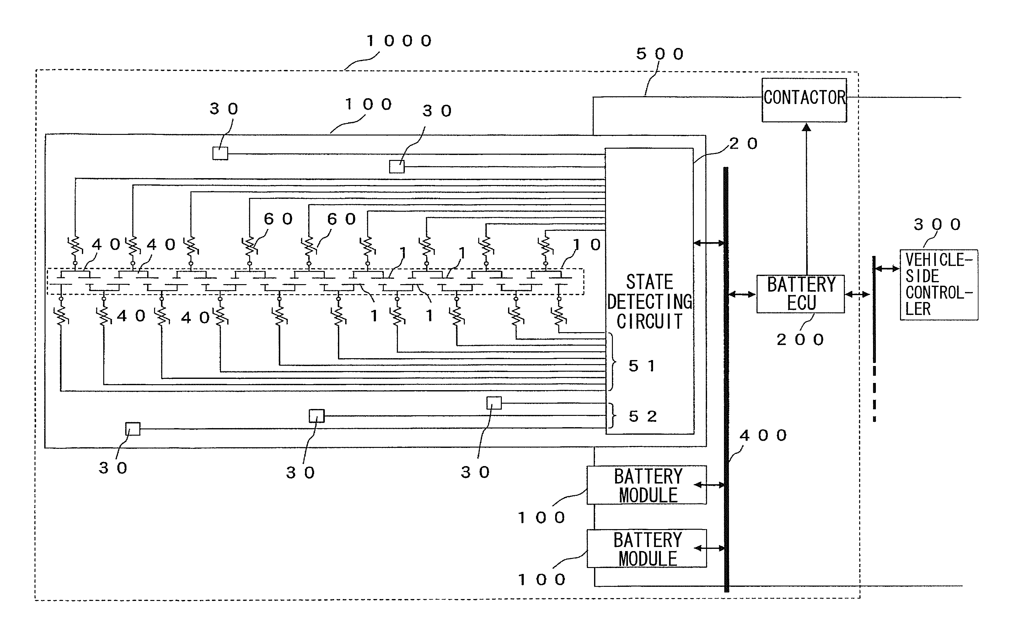
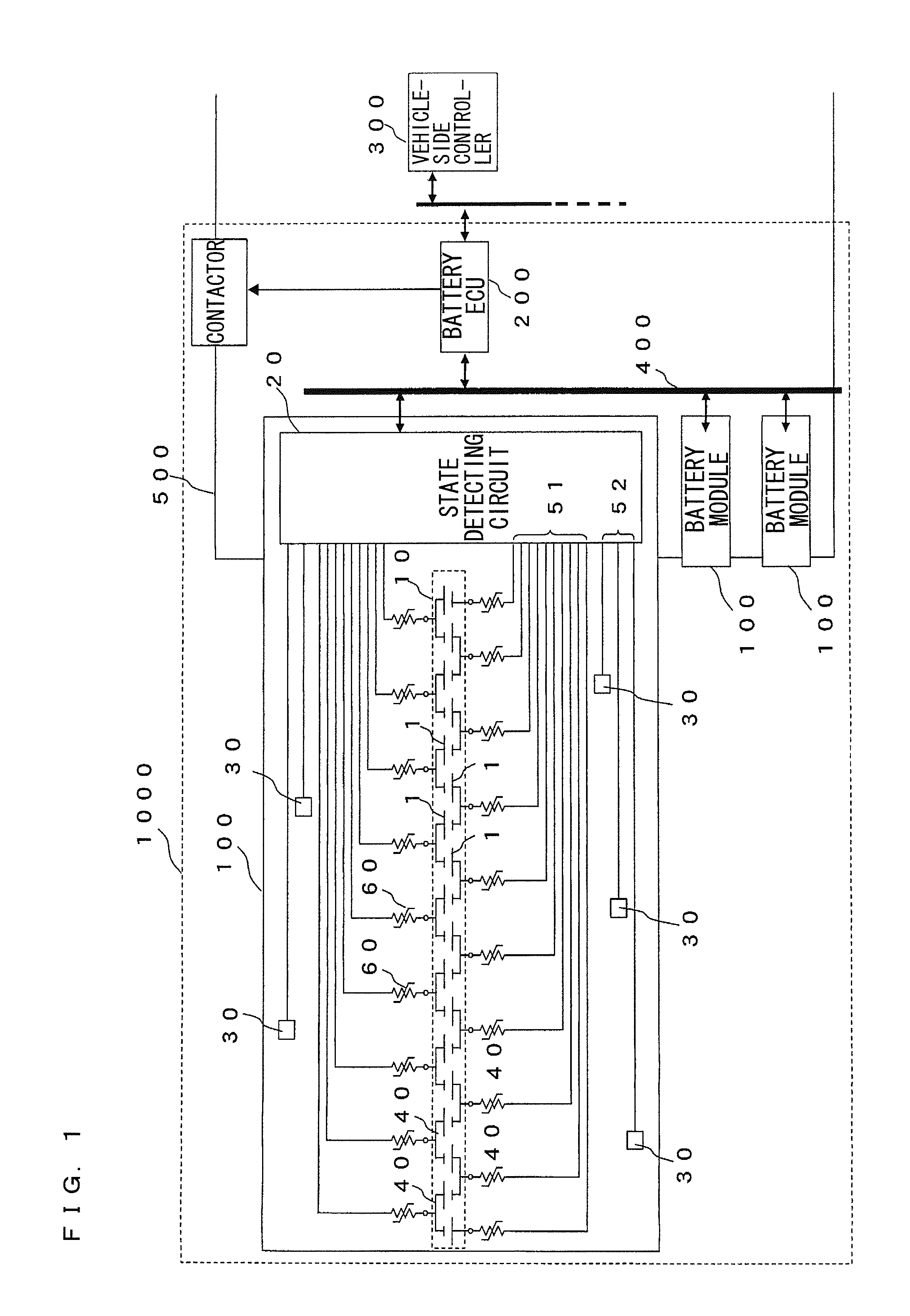
[0091]First, description will be made of circuits and functions in an inventive example of a battery system using a battery module of the present invention with reference to FIG. 1. FIG. 1 shows a circuit diagram of the battery system used in an HEV, an EV or the like. The battery system 1000 includes a plurality of battery modules 100, 100 . . . , a battery ECU 200, a communication line 400 and power lines 500. In the battery system 1000, the plurality of battery modules 100 are connected in series through the power lines 500, providing high voltage. Thus, the battery system 1000 supplies power for driving an automobile. When power of high capacity is required, the battery modules 100 are preferably connected in parallel. The plurality of battery modules 100, 100 . . . are connected to the battery ECU 200 through the communication line 400, and data communication is performed between the battery modules 100 and the battery ECU 200 for con...

third embodiment

[3] Third Embodiment

[0302]Next, description will be made of a battery system according to a third embodiment of the present invention by referring to differences from the battery system 1000A according to the foregoing second embodiment.

[0303]FIG. 28 is a schematic plan view of a battery system according to the third embodiment of the present invention.

[0304]As shown in FIG. 28, the battery system 1000B according to the third embodiment includes battery modules 100e, 100f, 100g, 100h instead of the battery modules 100a, 100b, 100c, 100d. The battery modules 100e, 100g have the same configurations, and the battery modules 100f, 100h have the same configurations.

[0305]Here, description will be made of the configuration of each of the battery modules 100e, 100f, 100g, 100h by referring to differences from the configuration of the foregoing battery module 100 (the battery module 100a, 100b, 100c, 100d).

[0306]FIG. 29 is a schematic plan view of the battery modules 100, 100e, 100f.

[0307]...

fourth embodiment

[4] Fourth Embodiment

[0343]Next, description will be made of a battery system according to a fourth embodiment of the present invention by referring to differences from the battery system according to the second embodiment.

[0344]FIG. 30 is a schematic plan view of the battery system according to the fourth embodiment of the present invention.

[0345]As shown in FIG. 30, the battery system 1000C according to the fourth embodiment includes battery modules 100i, 100j, 100k, 100l instead of the battery modules 100a, 100b, 100c, 100d. The battery modules 100i, 100k have the same configurations, and the battery modules 100j, 100l have the same configurations.

[0346]Here, description will be made of the configuration of each of the battery modules 100i, 100j, 100k, 100l by referring to differences from the configuration of the foregoing battery module 100 (the battery module 100a, 100b, 100c, 100d).

[0347]FIG. 31 shows schematic plan views of the battery modules 100, 100i, 100j.

[0348]First, d...


PUM

PropertyMeasurementUnit
irregularity width d1aaaaaaaaaa
shunt resistanceaaaaaaaaaa

Abstract

A battery block composed of a plurality of battery cells and a voltage detecting circuit (state detecting circuit) for detecting a voltage between terminals of each battery cell are included, and a flexible printed circuit board, in which a voltage detecting line for electrically connecting a positive electrode terminal or a negative electrode terminal of the battery cell and the voltage detecting circuit (state detecting circuit) is integrated with a substrate made or a flexible material, is provided.

Description

TECHNICAL FIELD[0001]The present invention relates to a battery module that includes a stack of a plurality of battery cells and to which a voltage detecting circuit is connected, a battery system and an electric vehicle.BACKGROUND ART[0002]In battery systems utilized for applications that require high power and high capacity batteries such as hybrid electric vehicles (HEV) and electric vehicles (EV), a plurality of battery cells are connected in series or in parallel for use. In such battery systems, voltages and currents of the battery cells are monitored in a battery ECU (Electronic Control Unit) in order to protect each battery cell by monitoring abnormalities of each battery cell such as excess current, overdischarge, overcharge, variation in an SOC (an index representing a charge state on percentage) of the battery cell. There has been proposed a battery system (Patent Document 1) as such a battery system. In the proposed battery system, a battery module is configured to inclu...

Claims


Application Information

Patent Timeline
Patent Type & Authority Applications(United States)
IPC IPC(8): B60L11/18H01M10/48H01M2/02H01M2/30H01M2/10H01M2/00H01M2/20B60L3/00H01M50/209H01M50/284H01M50/296H01M50/503H01M50/505H01M50/522H02J7/00H02J7/02
CPCH01M2/1077H01M2/206Y02T10/7011H01M10/441H01M10/482H01M10/0525Y02E60/10H01M50/522H01M50/209H01M50/284H01M50/505H01M50/296H01M50/503H01M10/48G01R31/3835H01M10/425H01M50/545H01M2220/20Y02T10/70
Inventor NISHIHARA, YOSHITOMOKISHIMOTO, KEIJIOHKURA, KAZUMITAGUCHI, KENJI
Owner PANASONIC ENERGY CO LTD
Why Eureka
Try Eureka