

Pneumatic tire
Active Publication Date: 2012-02-02
YOKOHAMA RUBBER CO LTD
View PDF6 Cites 22 Cited by
- Summary
- Abstract
- Description
- Claims
- Application Information
AI Technical Summary
Benefits of technology
[0022]With the present technology, a pneumatic tire is provided in which an object can be attached to an inner surface thereof via a mechanical fastener, wherein the obtained engagement force thereof is great and the engagement force is essentially free of variations (positional variation within the tire and variation from tire to tire). Furthermore, with the provided pneumatic tire, the engagement force deteriorates / declines minimally over time due to extreme usage conditions including repetitive deformation and compaction over an extended period of time caused by tire rotation at high speeds in a state of relatively elevated temperatures; and a desired engagement force can be maintained over an extended period of time.
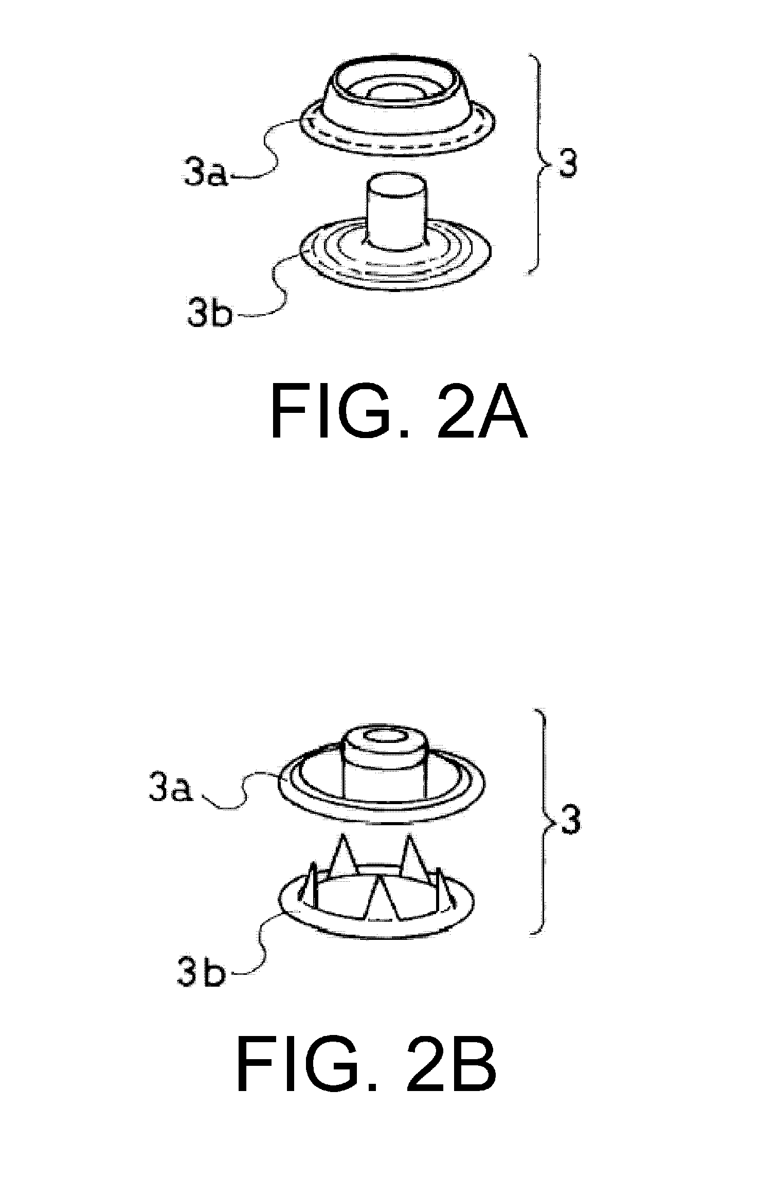
[0023]With the present technology, in addition to the effects provided by the technology described above, a pneumatic tire is provided in which the first fastener includes at least two members, the two members being fixed and forming the first fastener by sandwiching a tire member or a tire reinforcing member. Thereby, the fixing is firm, superior durability is obtained, and the desired engagement force can be maintained over an extended period of time.
[0024]With the present technology, in addition to the effects provided by the technology described above, a pneumatic tire is provided in which dimensions of the fastener are neither excessively large nor excessively small. Therefore, even when subjected to high pressure loads when vulcanizing the tire, the fastener does not deform or sink into the tire. Additionally, stability is excellent due to the fastener having suitable dimensions, and durability with regards to severe use over extended periods of time is high. As a result, the desired engagement force can be maintained for an even longer period of time.
[0025]With the present technology, in addition to the effects provided by the technology described above, a pneumatic tire is provided in which greater and more stable engagement force can be displayed because the engagement force of the surface fastener is combined. Particularly, by engaging the pair of mechanical fasteners, a pneumatic tire can be provided in which the surface fasteners can be automatically engaged at an optimal engagement position as desired, and the maximum effectiveness of the engagement force of both components (the mechanical fasteners and the surface fasteners) can be displayed. Additionally, because surface fasteners are generally inexpensive, using both components can lead to overall costs being reduced while high-precision engagement positioning and high engagement force are realized.
[0026]With the present technology, in addition to the effects provided by the technology described above, a pneumatic tire is provided in which greater and more stable engagement force can be displayed due to the engagement force provided by the pair of mechanical fasteners. Particularly, a high degree of effectiveness is displayed when a weight or volume of an object having desired functionality to be attached to a tire inner surface is, to a certain degree, great.
[0027]With the present technology, a pneumatic tire is provided in which an object having desired functionality is attached to a tire inner surface while realizing great engagement force and superior durability.
Problems solved by technology
However, with the surface fasteners proposed in the prior references, a state in which the individual engaging elements of the surface fastener are engaged is not ideal due to the inner circumferential surface of the pneumatic tire being an annular, curved surface.
As a result, in some cases the expected engagement force is not obtained.
Additionally, partial physical deterioration and deterioration / declining over time of the engagement force of an entirety of the surface fastener accompanying the progression of the partial physical deterioration occurs as a result of repetitive deformation and compaction over an extended period of time caused by rotation at high speeds in a state of relatively elevated temperatures.
This has led to cases in which difficulties have been met in maintaining a desired engagement force over an extended period of time.
The engagement force deteriorates / declines minimally over time due to extreme usage conditions including repetitive deformation and compaction over an extended period of time caused by tire rotation at high speeds in a state of relatively elevated temperatures.
Method used
View moreImage
Smart ImageViewing Examples

Examples
working examples
[0062]Hereinafter, specific configurations and effects of the present technology will be described using a Working Example and a Comparative Example.
Login to View More PUM
 Abstract
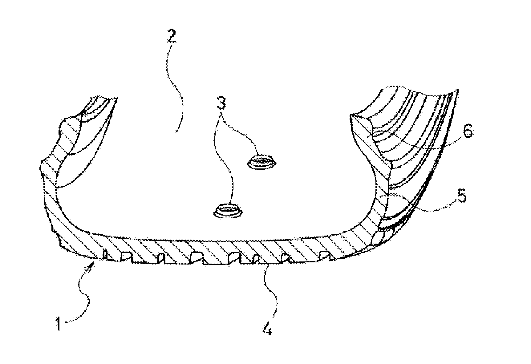
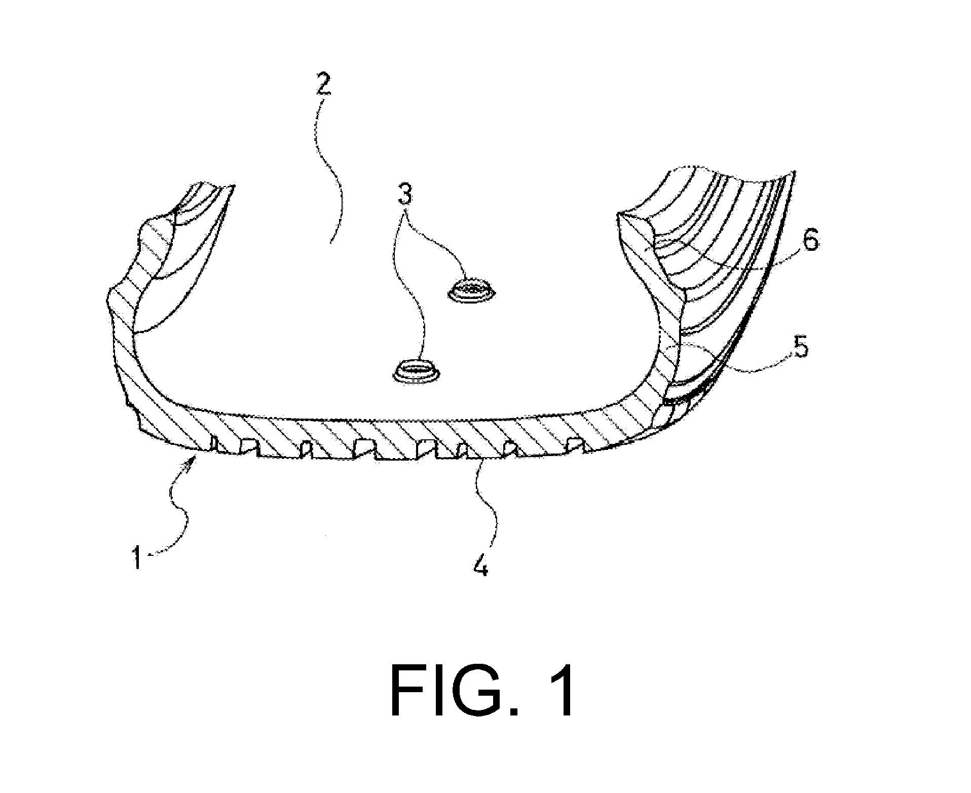
A pneumatic tire including a separatable pair of mechanical fasteners wherein a first fastener of the pair of mechanical fasteners is provided on a tire inner surface. In this pneumatic tire, the obtained engagement force of the pair of mechanical fasteners is great and is essentially free of variations (positional variation within the tire and variation from tire to tire); the engagement force deteriorates / declines minimally over time due to extreme usage conditions including repetitive deformation and compaction over an extended period of time caused by tire rotation at high speeds in a state of relatively elevated temperatures; and the desired engagement force can be maintained over an extended period of time.
Description
PRIORITY CLAIM[0001]Priority is claimed to Japan Patent Application Serial No. 2010-167839 filed on Jul. 27, 2010.BACKGROUND[0002]1. Technical Field[0003]The present technology relates to a pneumatic tire, and particularly to a pneumatic tire in which a method for attaching an object to an inner surface of a pneumatic tire is realized.[0004]2. Related Art[0005]In recent years, various attempts at disposing objects having various functions on an inner circumferential surface of pneumatic tires have been made.[0006]For example, an attaching method has been proposed in which tire tags (radio frequency identification tags), chips, or the like are attached to an inner liner or the like of a green tire using a surface fastener such as a hook and loop fastener, a hook and hook fastener, or the like (Japanese Unexamined Patent Application Publication (translation of PCT application) No. 2005-517581).[0007]Additionally, a pneumatic tire has been proposed in which a surface fastener is vulcan...
Claims
Login to View More Application Information
Patent Timeline
 IPC IPC(8): B60C19/00B60C5/00
CPCB60C23/0493Y10T152/10495B29D2030/0072Y10T152/10891Y10T152/10927
InventorTANNO, ATSUSHIKUWAJIMA, MASATOSHI
OwnerYOKOHAMA RUBBER CO LTD