Grip ring assembly

Inactive Publication Date: 2012-02-02
KRAUSZ INDS DEVMENT
View PDF6 Cites 28 Cited by
  • Summary
  • Abstract
  • Description
  • Claims
  • Application Information

AI Technical Summary

Benefits of technology

[0005]The present invention seeks to provide an improved grip ring assembly with axial fasteners that prevent axial separation of the pipes being coupled, as is described more in deta

Problems solved by technology

However, there are applications which require significant f

Method used


Image

  • Grip ring assembly
  • Grip ring assembly
  • Grip ring assembly

Examples


Embodiment Construction

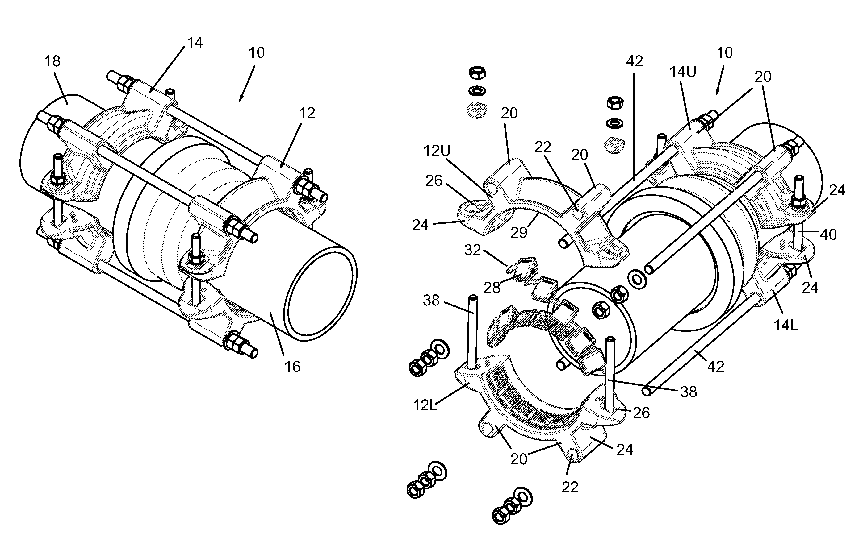
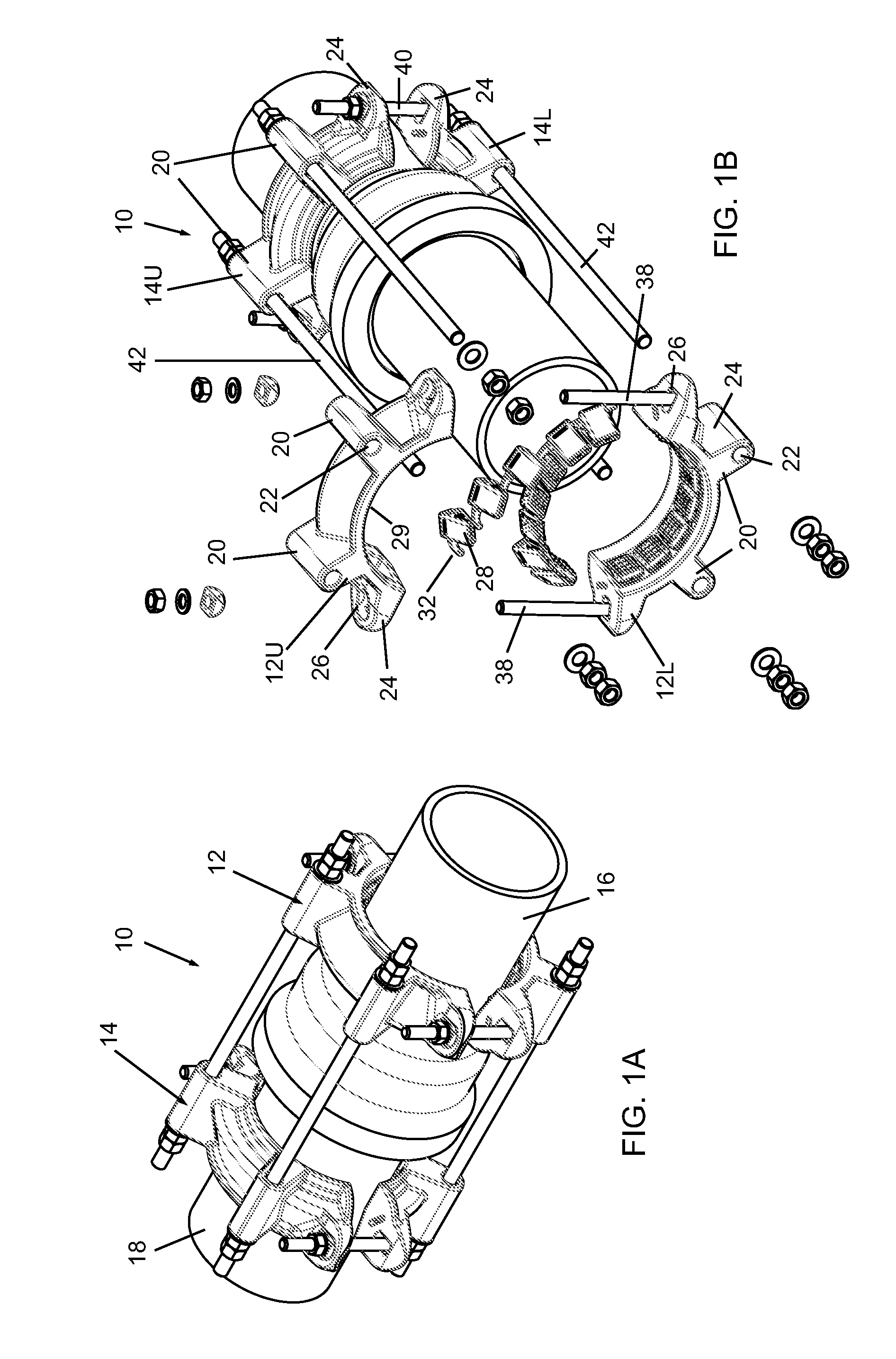
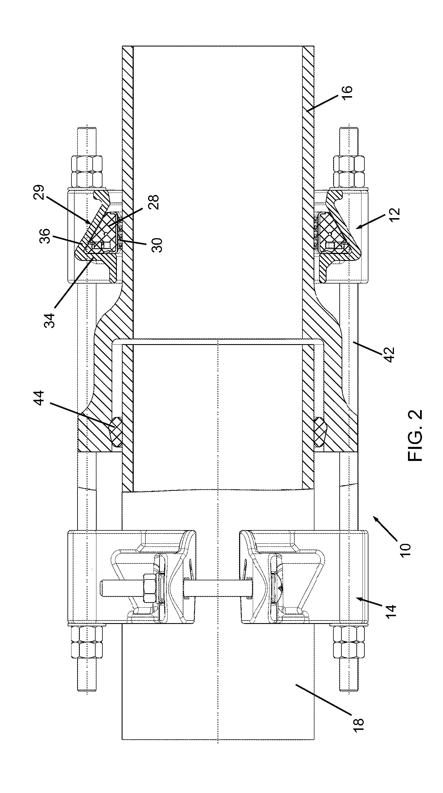
[0014]Reference is now made to FIGS. 1A, 1B and 2, which illustrate a grip ring assembly 10, constructed and operative in accordance with a non-limiting embodiment of the present invention.

[0015]Grip ring assembly 10 includes at least one yoke assembly. In the illustrated embodiment, there are two such yoke assemblies—first and second yoke assemblies 12 and 14 axially spaced apart for assembling on to pipes 16 and 18 that are to be coupled axially to one another. Alternatively, there may be just one yoke assembly which is assembled on one pipe and connected to a flange or other mechanical part. Each yoke assembly 12 and 14 includes at least two yokes, referred herein as an upper yoke 12U / 14U and a lower yoke 12L / 14L. It is to he understood that, particularly for large diameter pipes, there may be three, four, five or more yokes. so the terms “upper” and “lower” are not limited to being actually upper or lower in the sense of up and down.

[0016]Each of the yoke assemblies includes one...


PUM


Abstract

A grip ring assembly including at least one yoke assembly for assembling on to a pipe that is to be coupled axially to a mechanical part, the at least one yoke assembly including an upper yoke and a lower yoke, wherein the at least one yoke assembly includes at least one axial fastener receiving member and the upper and lower yokes includes at least one transverse fastener receiving member generally transverse to the at least one axial fastener receiving member, a plurality of grip elements tightenable against outer surfaces of the pipes, radially spaced from one another and disposed along annular inner surfaces of the upper and lower yokes, at least one first transverse fastener operative to fasten the transverse fastener receiving members of the upper and lower yokes of the at least one yoke assembly to one another, and at least one axial fastener operative to fasten the at least one axial fastener receiving member to the mechanical part.

Description

FIELD OF THE INVENTION[0001]The present invention relates generally to grip rings for pipes, and particularly to a grip ring assembly with axial fasteners that prevent axial separation of the pipes being coupled.BACKGROUND OF THE INVENTION[0002]Many kinds of removable band-type couplings for pipes exist in the art. It is noted that throughout the specification and claims, the term “pipe” encompasses any kind of generally cylindrical object.[0003]For example, one commercially available type of pipe coupling is in the form of a grip ring. There is a plurality of wedge-shaped grip elements radially spaced from one another to form a ring. The grip elements are formed with teeth that face inwards towards the center of the ring. A clamp is provided, which when tightened in a direction transverse to the axial length of the pipe, press the grip ring against the surface of the pipe.[0004]However, there are applications which require significant force to prevent axial separation of the pipes ...

Claims


Application Information

Patent Timeline
IPC IPC(8): F16L19/06
CPCF16L21/08
Inventor KRAUSZ, ELIEZERCHIPROOT, AVI
Owner KRAUSZ INDS DEVMENT
Why Eureka
Try Eureka