Jet engine Anti-icing and noise-attenuating air inlets

Active Publication Date: 2017-01-12
THE BOEING CO
View PDF11 Cites 14 Cited by
  • Summary
  • Abstract
  • Description
  • Claims
  • Application Information

AI Technical Summary

Benefits of technology

[0010]The manifold and the plenum can be separately supplied with high temperature engine bleed air at different pressures and flow rates so as not only to provide a more uniform distribution o

Problems solved by technology

While these systems can provide satisfactory performance in a variety of flying conditions, they are not without some drawbacks.
For example, the hot engine bleed air may not be uniformly distributed throughout the inlet under all flying conditions, resulting in both engine and anti-icing inefficiencies.
This not only can substa

Method used


Image

  • Jet engine Anti-icing and noise-attenuating air inlets
  • Jet engine Anti-icing and noise-attenuating air inlets
  • Jet engine Anti-icing and noise-attenuating air inlets

Examples


Example

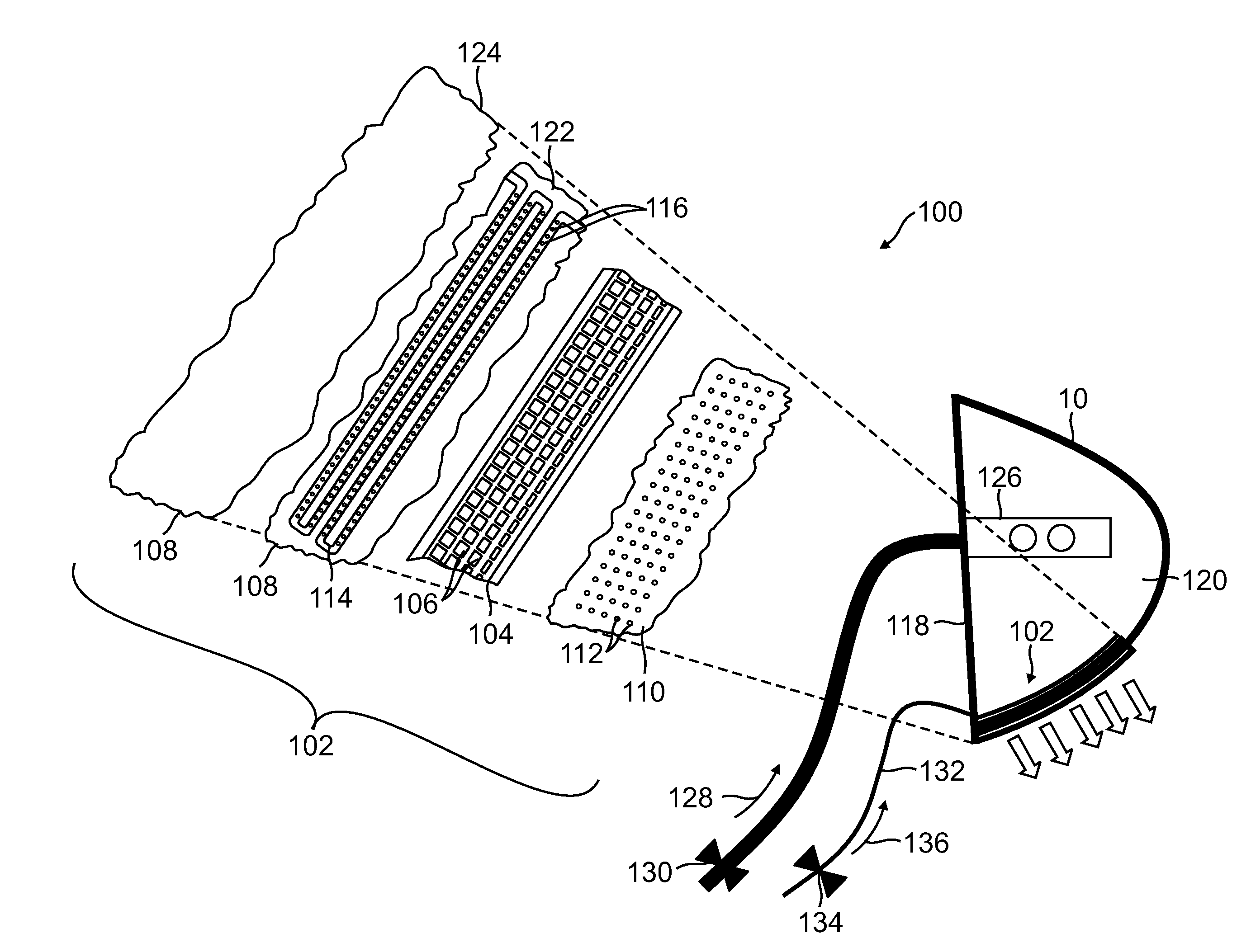
[0021]In accordance with embodiments of the present disclosure, novel systems and methods are provided for designing, making and using jet engine air inlets that prevent inlet icing, and optionally, attenuate forwardly propagating engine noise, while overcoming the air distribution and internal overpressurization problems of prior art systems.

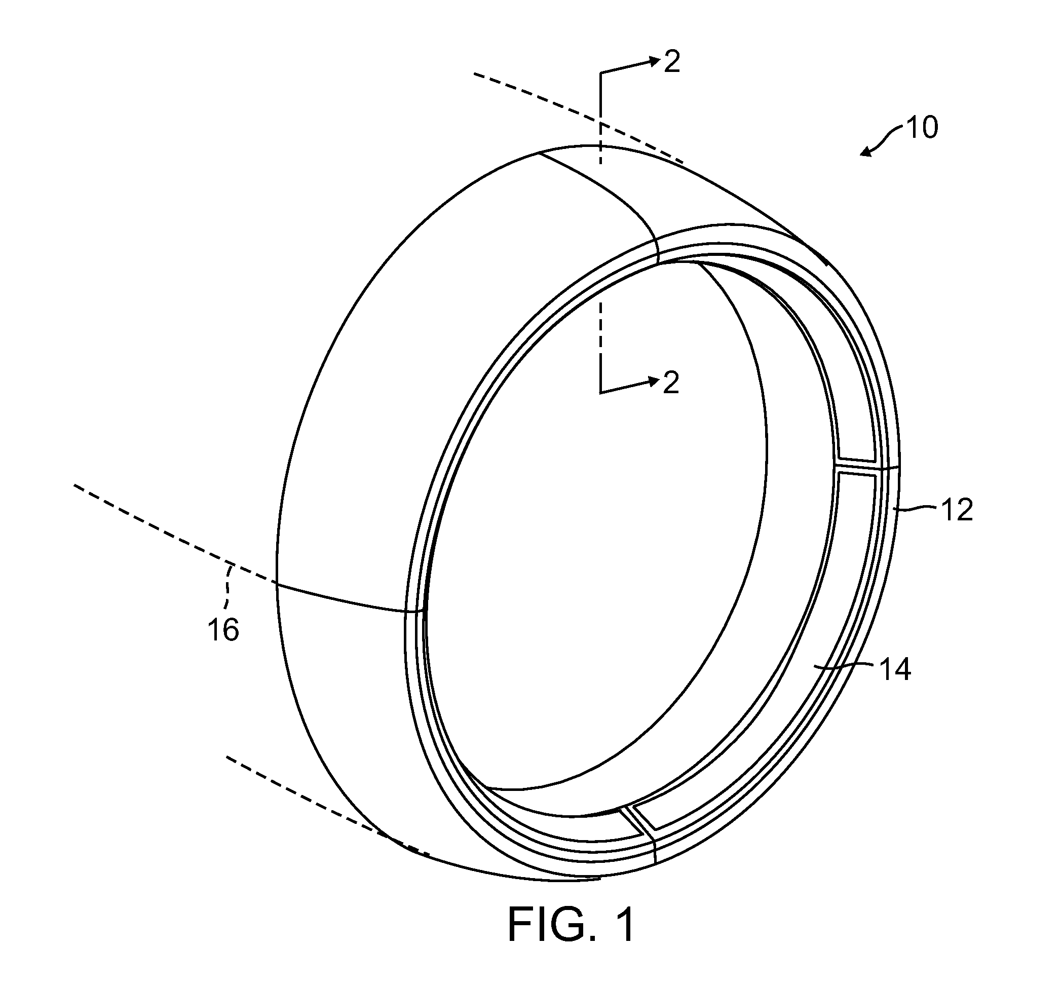
[0022]FIG. 1 is an upper, front and right side perspective view of a typical subsonic jet engine air inlet 10, showing a “highlight”12, i.e., the most upstream end of the inlet 10, as well as a porous inlet “lip skin”14 of an anti-icing and engine-noise-attenuating system disposed therein. The inlet 10 comprises a front end of a streamlined engine “nacelle”16 (indicated by dashed lines) disposed rearwardly of the inlet 10 that shrouds an associated jet engine (not illustrated). As illustrated in FIG. 1, the inlet 10 is generally round in transverse cross-section, has a recurvate inside-to-outside surface, in the manner of the nose portion of an...


PUM


Abstract

An embodiment of a jet engine air inlet providing anti-icing, and optionally, engine noise reduction, includes a rigid frame defining a gridwork of contiguous cells. A cap skin has an outer surface sealingly attached to an inner surface of the frame. An outer skin has an inner surface sealingly attached to an outer surface of the frame and contains a plurality of openings therein.
Each of the openings is disposed in fluid communication with a corresponding one of the cells, each of which can comprise a Helmholtz resonator. A serpentine manifold extends adjacent to an inner end of each of the cells and contains a plurality of apertures in a sidewall thereof, each of which is disposed in fluid communication with a corresponding one of the cells.

Description

TECHNICAL FIELD[0001]This disclosure generally relates to jet aircraft engines, and more particularly, to jet engine air inlets that function to prevent inlet icing and attenuate engine noise.RELATED ART[0002]Most modern commercial aircraft are powered by gas turbine or “jet” engines. All jet engines have an air inlet that directs intake air into the engine. The inlet is disposed upstream of the compressor stages of the engine, and forms the front end of a streamlined fairing, or “nacelle,” that surrounds the engine. On a typical subsonic aircraft, the air inlet is generally round in transverse cross-section, has a continuous, recurvate inside-to-outside surface, and a thickness that varies continuously from the most downstream end of the inlet to the most upstream end, or “highlight,” thereof.[0003]The air inlet of an engine of a subsonic commercial jet aircraft typically incorporates a lining or “lip” on the inner surface of the inlet that functions in conjunction with an anti-ici...

Claims


Application Information

Patent Timeline
IPC IPC(8): B64D33/02F02C7/047F02C7/045
CPCB64D33/02F02C7/045F02C7/047F05D2250/185B64D2033/0233F05D2230/60B64D2033/0206F05D2260/963F05D2250/283
Inventor MACKIN, STEVE G.LEISTEN, BRADLEY S.
Owner THE BOEING CO
Why Eureka
Try Eureka