Buffer for absorbing impacts

Active Publication Date: 2011-09-22
ACLA WERKE
View PDF7 Cites 8 Cited by
  • Summary
  • Abstract
  • Description
  • Claims
  • Application Information

AI Technical Summary

Benefits of technology

[0016]This has the advantage that the constructional height can be further reduced, while the energy absorption capacity remains constant or can be further increased.
[0017]The lateral surfaces of the additional element can extend at an angle from 20° to 80°, preferably from 30° to 60°, relative to force take-up axis of

Problems solved by technology

Conventional buffers as heretofore used have the disadvan

Method used


Image

  • Buffer for absorbing impacts
  • Buffer for absorbing impacts
  • Buffer for absorbing impacts

Examples


Example

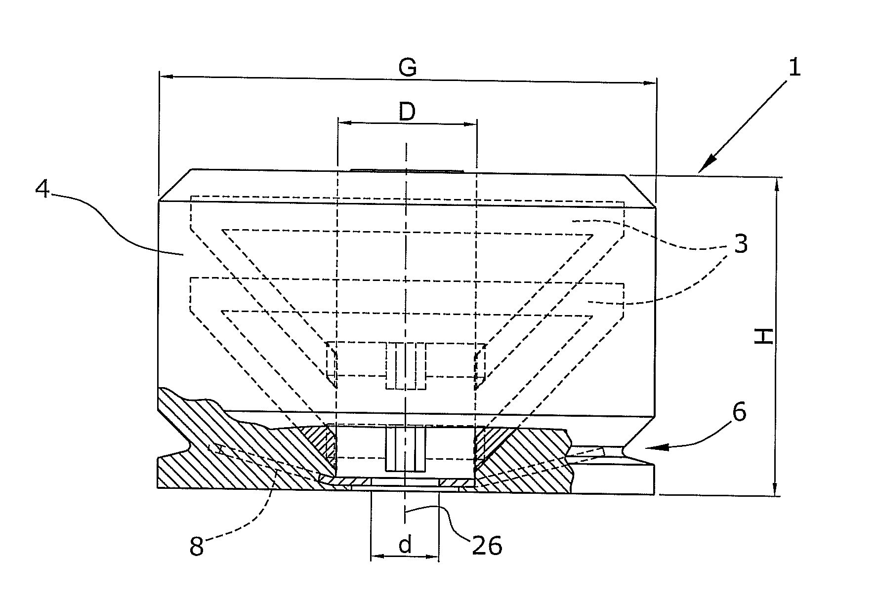
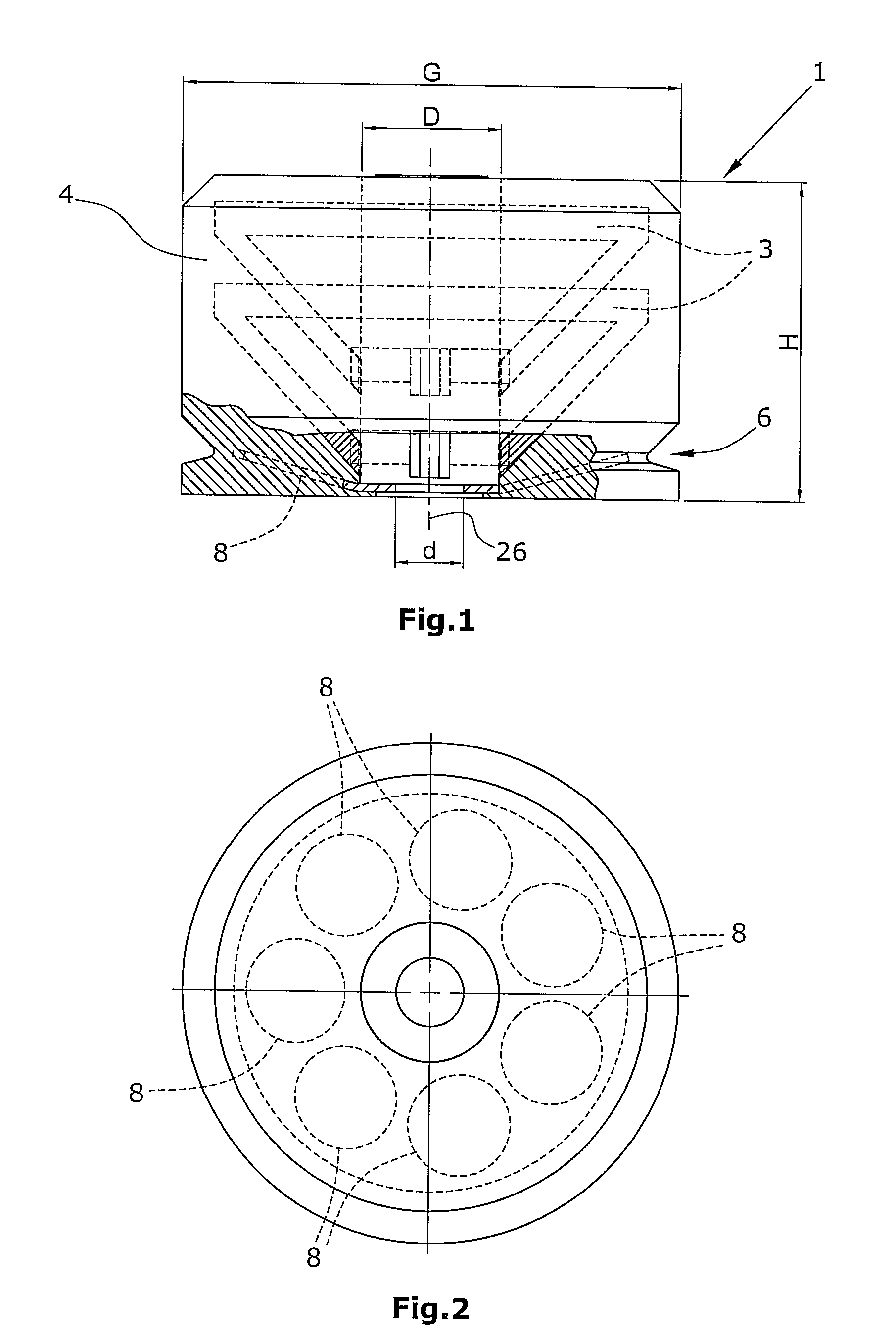
[0028]In FIG. 1, a buffer 1 for absorbing impacts is shown in lateral view. Buffer 1 has a cylindrical shape. Further, buffer 1 comprises a buffer element 4. Said buffer element 4 is elastic and volume-compressible. Preferably, buffer element 4 is compressible by up to 80 to 90% in the force direction. Further, buffer element 4 preferably comprises an air content from 60 to 70%. Buffer element 4 is made of a foamed plastic material. With preference, buffer element 4 is made of a foamed polyurethane elastomer.

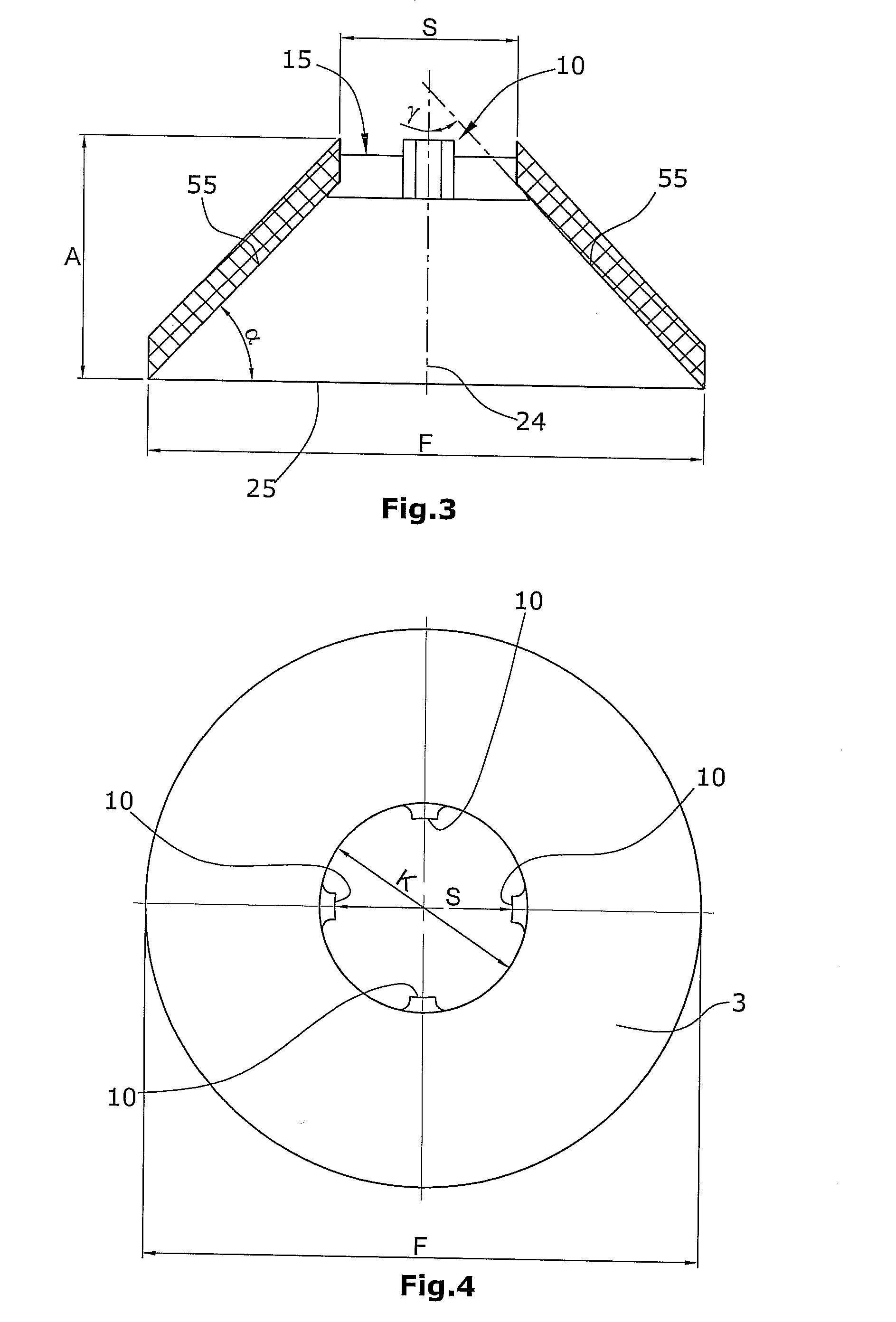
[0029]In the presently described embodiment, buffer element 4 comprises two additional elements 3. Said additional elements 3 are enclosed within buffer element 4. The additional elements 3 are arranged within buffer element 4 in a floating manner. Each of the additional elements 3 has the shape of the hollow frustum of a circular cone. The additional element is preferably a frustum of a right circular cone. The cone axis of the frustum of a circular cone extends along the longi...


PUM


Abstract

In a buffer (1) for absorbing impacts, which comprises an elastic buffer element (4) made of a material having a first e-module, and a force take-up axis, the buffer element (4) being compressible at least in the direction of said force take-up axis, it is provided that at least one additional element (3) having a second e-module is enclosed in said buffer element (4), the second e-module being larger than the first e-module.

Description

BACKGROUND OF THE INVENTION[0001]1. Field of the Invention[0002]The present invention relates to a buffer for absorbing impacts according to the precharacterizing part of claim 1.[0003]2. Description of the Prior Art[0004]Buffers of the type heretofore used for impact absorption consist of a volume-compressible, elastic buffer element having a first e-module. These buffers are e.g. buffers for an elevator cab or for use as a counterweight of an elevator cab. The buffers provided for such purposes are referred to as detachable bumpers. Such buffers are frequently installed in the pit of an elevator shaft.[0005]The buffer could also be used as a safety buffer in crane building, or as a buffer in the automotive field.[0006]Conventional buffers as heretofore used have the disadvantage that their constructional height is relatively large. In recent years, however, continuous efforts are undertaken, e.g. in the installation of elevators, to reduce the size of the shaft pit.[0007]Thus, it ...

Claims


Application Information

Patent Timeline
IPC IPC(8): B66B5/28F16F7/00F16F3/093
CPCF16F3/093B66B5/282
Inventor KIEFFER, GERHARD
Owner ACLA WERKE
Why Eureka
Try Eureka