Separation device

a separation device and a technology for smoking rods, applied in the direction of meat/sausage hanging up, coin-freed apparatus, tableware, etc., can solve the problems of additional time and cost, and achieve the effect of safe and reliable separation of smoking rods

Active Publication Date: 2016-10-25
POLY CLIP SYST
View PDF43 Cites 2 Cited by
  • Summary
  • Abstract
  • Description
  • Claims
  • Application Information

AI Technical Summary

Benefits of technology

[0007]Thus, it is an object of the present invention to provide a separation device and a method with which the above mentioned drawbacks can be overcome and with which a safe and reliable separation of smoking rods may be assured.
[0010]In the inventive separation device, a first discharge unit is provided, for discharging a single rod-like element out of the plurality of rod-like elements stored in the storage space, out of the storage space, along a moving path in a discharge direction directed at least approximately opposite to the feeding direction, into a discharge area being located in the upper region of the storage space. While discharging the separated smoking rod to the discharge area being located in the upper region of the storage space by the first discharge unit according to this invention, effective separation may be achieved. Moreover, the discharge of the smoking rod is not affected by the weight of the plurality of smoking rods remaining in the storage space.
[0011]In principle, the first opening can be used for feeding and discharging the smoking rods to and from the storage space. In order to allow a separate feeding or discharging of a smoking rod from a discharging or feeding of another smoking rod, it is favorable that a second opening is provided in the upper region of the storage space for at least discharging the rod-like element separated by the first discharge unit. Such a discharge opening in the upper region of the separation device allows further a flexible connection of the separation device to the hanging line and a reduced construction height of the production line including the inventive separation device.
[0013]The first discharge unit may comprise at least one telescopic operating device having an upper operating end, which is reversibly vertically movable between a lower and an upper position, thereby separating on its way to the upper position one rod-like element out of the plurality of rod-like elements stored in the storage space. By moving the upper end of the telescopic operating device to its upper position, the separation of a single rod-like element is assured, and a blocking of the separated rod-like element by other rod-like elements is avoided.
[0016]In order to increase the accuracy of separation and for preventing a separated rod-like element from falling off the telescopic operating device of the first discharge unit, the first discharge unit comprises a second telescopic operating device having an upper operating end which is reversibly vertically movable between a lower and an upper position, thereby separating on its way to the upper position one rod-like element out of the plurality of rod-like elements stored in the storage space.
[0027]The inventive method for separating a rod-like element from a plurality of rod-like elements provides the same advantages as disclosed in conjunction with the inventive separation device.

Problems solved by technology

Moreover, in case that the smoking rod positioned adjacent to the releasing opening, is blocked or engaged by a further smoking rod, no smoking rod may be fed to the hanging line, causing additional time and costs.

Method used


Image

  • Separation device
  • Separation device
  • Separation device

Examples


Embodiment Construction

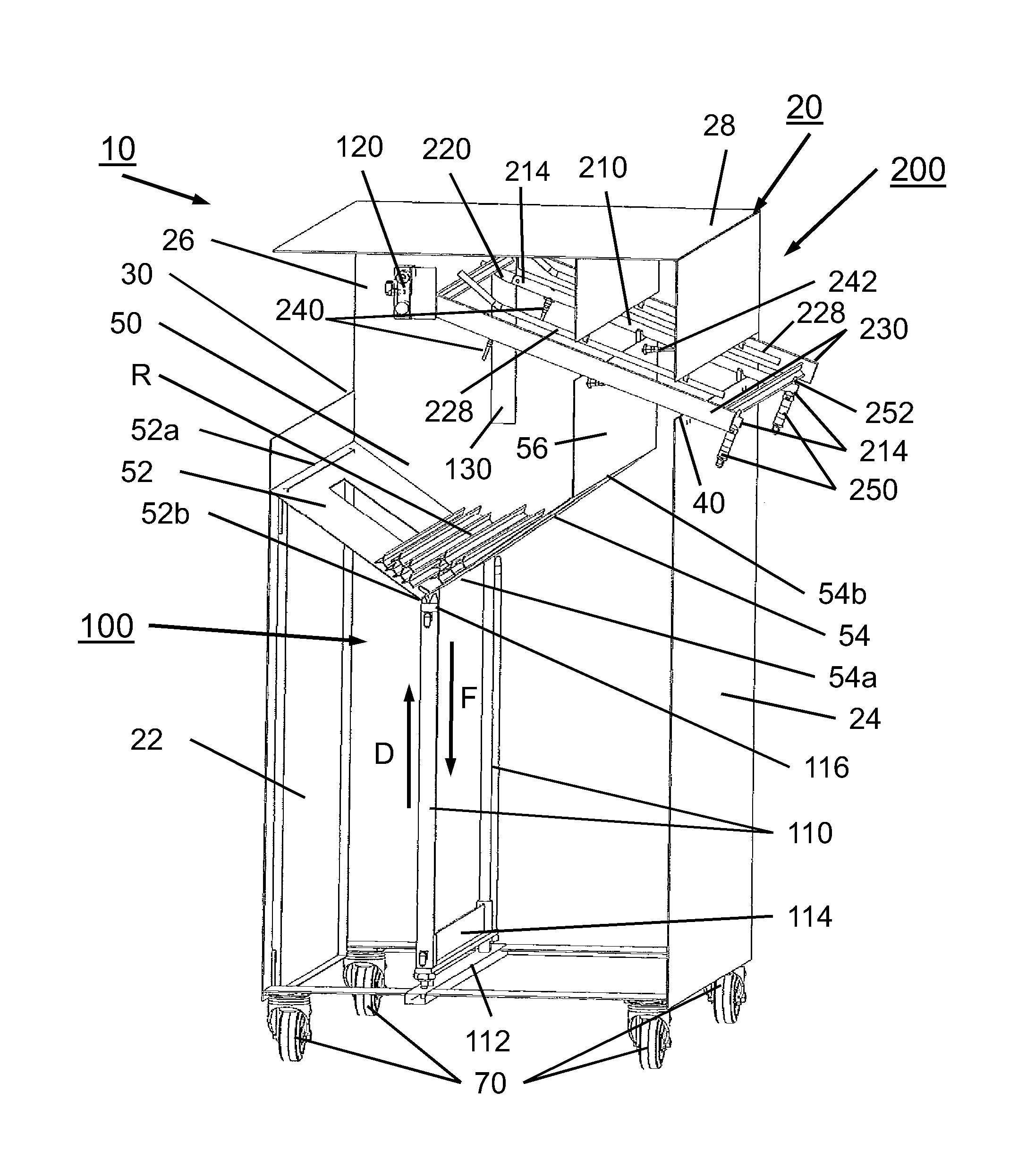
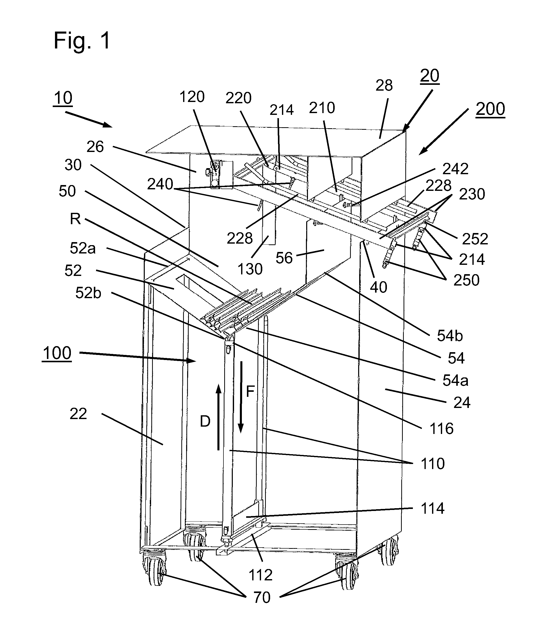
[0034]FIG. 1 shows a schematic and perspective view of an embodiment of a separation device according to the present invention, with the first discharge unit 100 in the upper position.

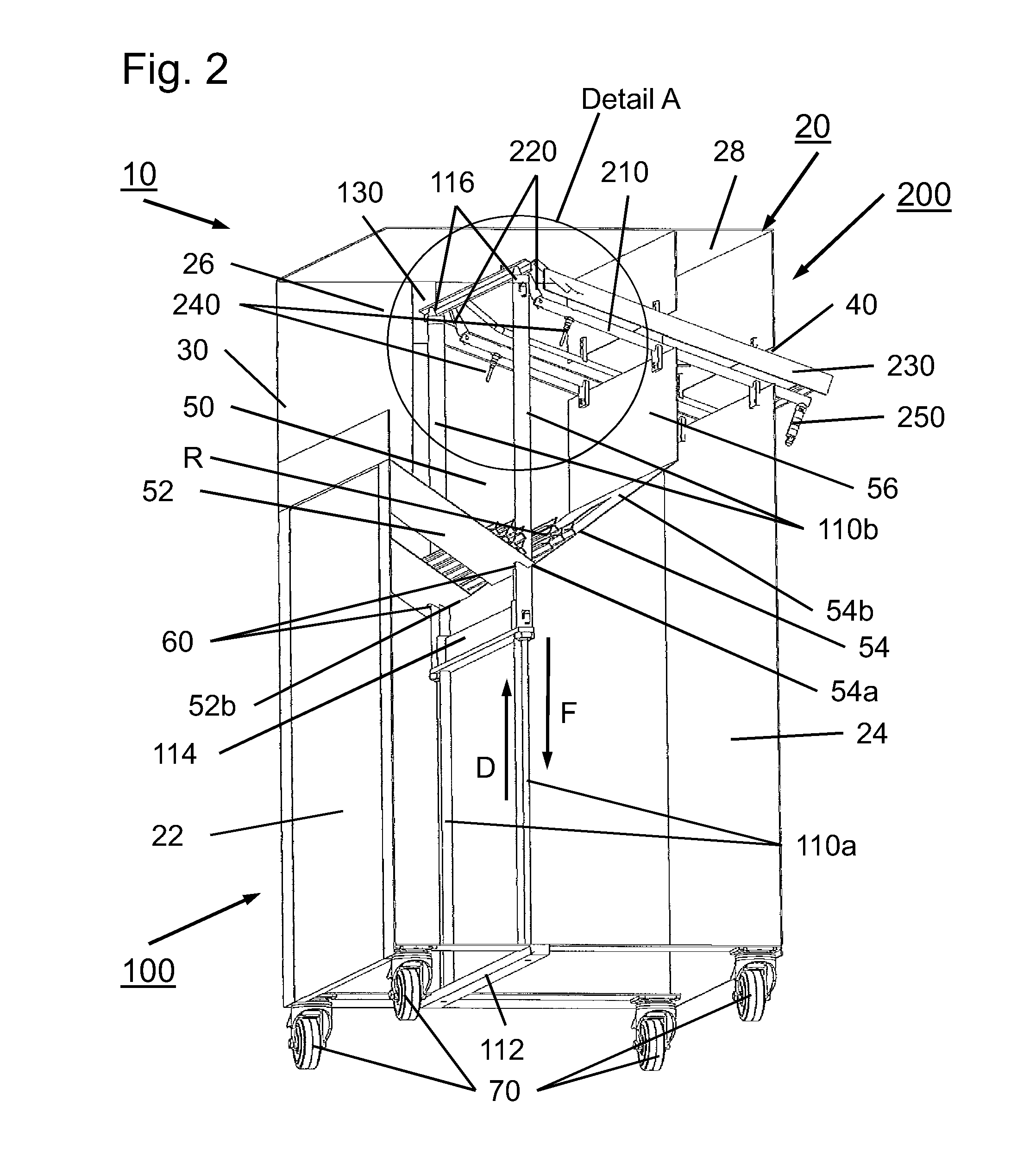
[0035]The separation device 10 comprises the first discharge unit 100 and a second discharge unit 200. First and second discharge units 100, 200 are accommodated in a common housing 20.

[0036]Housing 20 consists of a front wall 22, a rear wall 24, two identical side walls 26 and a top wall 28. For clarification matters, in FIGS. 1 and 2, only one of side walls 26 is shown, namely the rearmost side wall 26. In its upper region, front wall 22 comprises a first squared opening 30. A second opening 40 having a squared shape, is arranged in the upper region of rear wall 24. In FIG. 1, opening 30 in front wall 22 is shown as to be larger than opening 40 in rear wall 24. Naturally, openings 30, 40 may also be of the same size, or opening 40 may be larger than opening 30. Housing 20 further comprises frame elem...


PUM


Abstract

The present invention concerns a separation device for separating a rod-like element from a plurality of rod-like elements stored in a storage. The separation device may include a storage space having an approximately V-shaped cross section, for storing a plurality of at least approximately horizontally aligned rod-like elements, wherein the storage space includes at least a front wall element, a rear wall elements, and two side wall elements, having a bottom section and a top section. Moreover, a first discharge unit may be included for discharging a single rod-like element out of the plurality of rod-like elements stored in the storage space.

Description

[0001]This application claims priority to, and the benefit of, European Patent Application No. 10 004 816.4-1260 filed May 6, 2010, which is hereby incorporated by reference.BACKGROUND OF THE INVENTION[0002]The present invention relates to a separation device according to the preamble of independent claim 1 for separating a rod-like element, like a smoking rod, from a plurality of rod-like elements, like smoking rods, stored in a storage as well as a method according to the preamble of independent claim 14 for separating a rod-like element, like a smoking rod, from a plurality of rod-like elements, like smoking rods, stored in a storage.[0003]In particular, the present invention relates to a separation device for separating a rod-like element, like a smoking rod, from a plurality of rod-like elements, like smoking rods, stored in a storage. The separating device comprises a storage space having an approximately V-shaped cross section, for storing a plurality of at least approximatel...

Claims


Application Information

Patent Timeline
Patent Type & Authority Patents(United States)
IPC IPC(8): A24F15/04G07F11/16A22C15/00A47G21/12B65G47/14
CPCA22C15/001A47G21/12B65G47/1478B65G2201/0217
Inventor WIEMER, PETERKESSLER, GUNTER
Owner POLY CLIP SYST
Why Eureka
Try Eureka