Female coupling element and a quick coupling including such an element

a technology of coupling elements and couplings, which is applied in the direction of couplings, water supply installations, transportation and packaging, etc., can solve the problems of increasing the cost of fabricating such couplings, and achieve the effect of limited fabrication costs

Active Publication Date: 2012-09-04
STAUBLI FAVERGES SA
View PDF10 Cites 13 Cited by
  • Summary
  • Abstract
  • Description
  • Claims
  • Application Information

AI Technical Summary

Benefits of technology

[0006]The invention seeks more particularly to remedy these drawbacks by proposing a female coupling element suitable for co-operating with a complementary male portion and enabling the male portion to be separated from the female element safely after a purging stage, while nevertheless presenting limited fabrication cost.

Problems solved by technology

As a result, obtaining determined sections for these clearance gaps would require the parts of the coupling to be of precise dimensions and that would considerably increase the cost of fabricating such a coupling.

Method used


Image

  • Female coupling element and a quick coupling including such an element
  • Female coupling element and a quick coupling including such an element
  • Female coupling element and a quick coupling including such an element

Examples


first embodiment

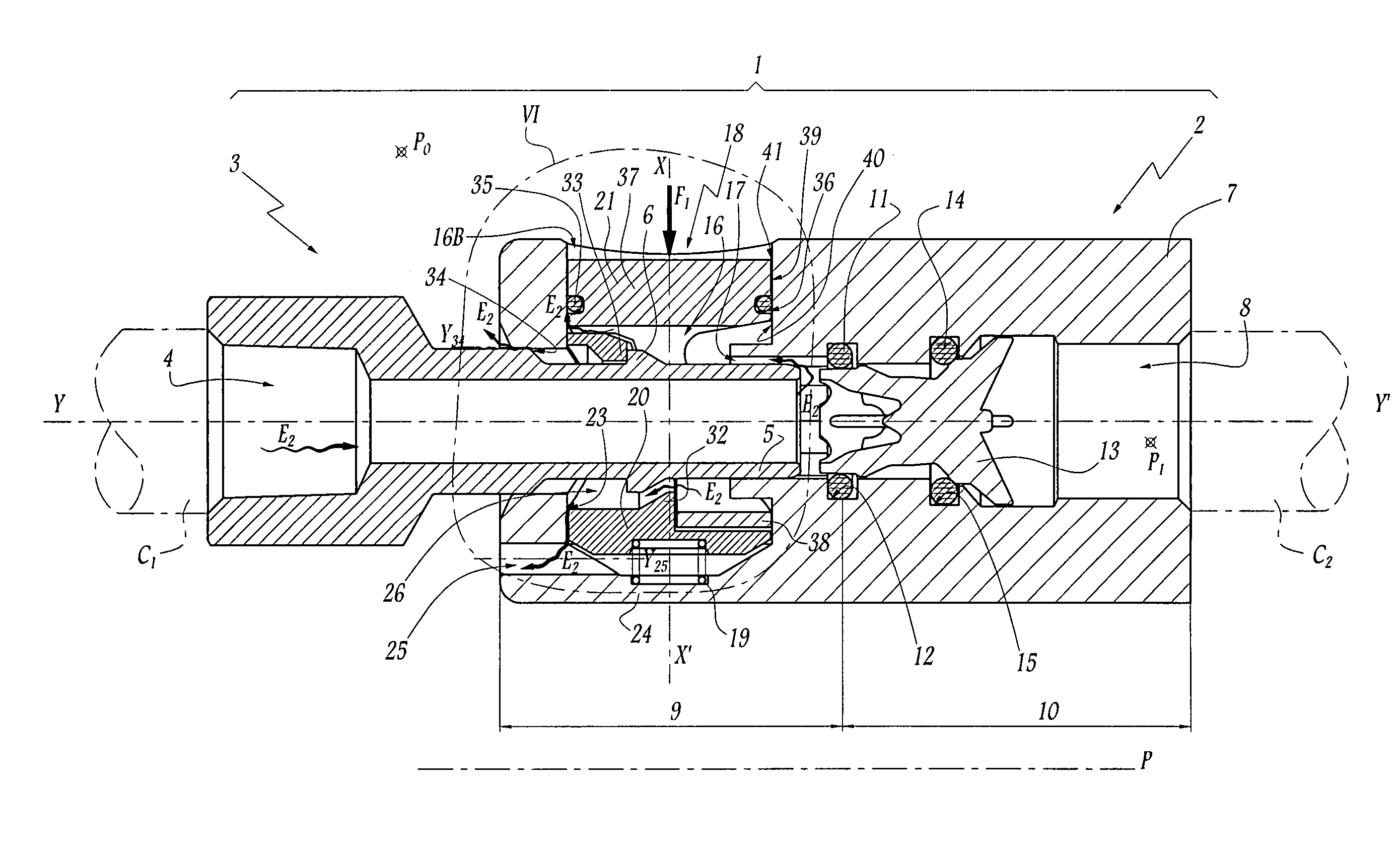
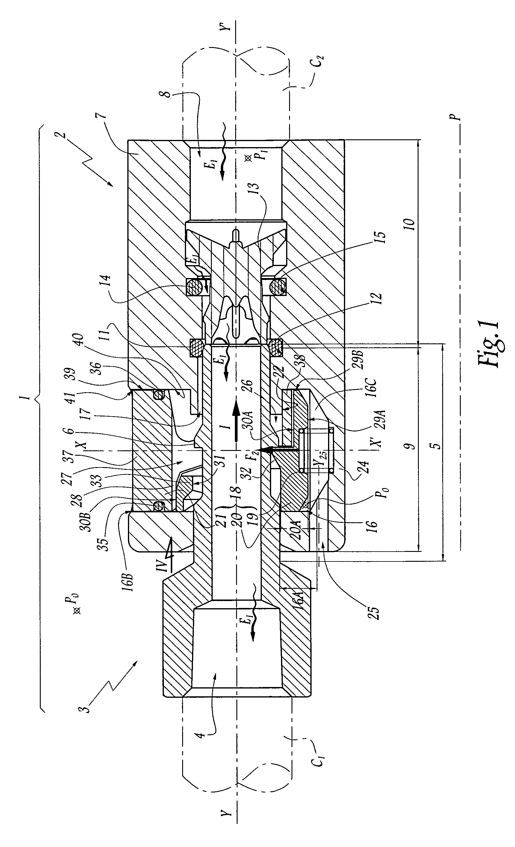
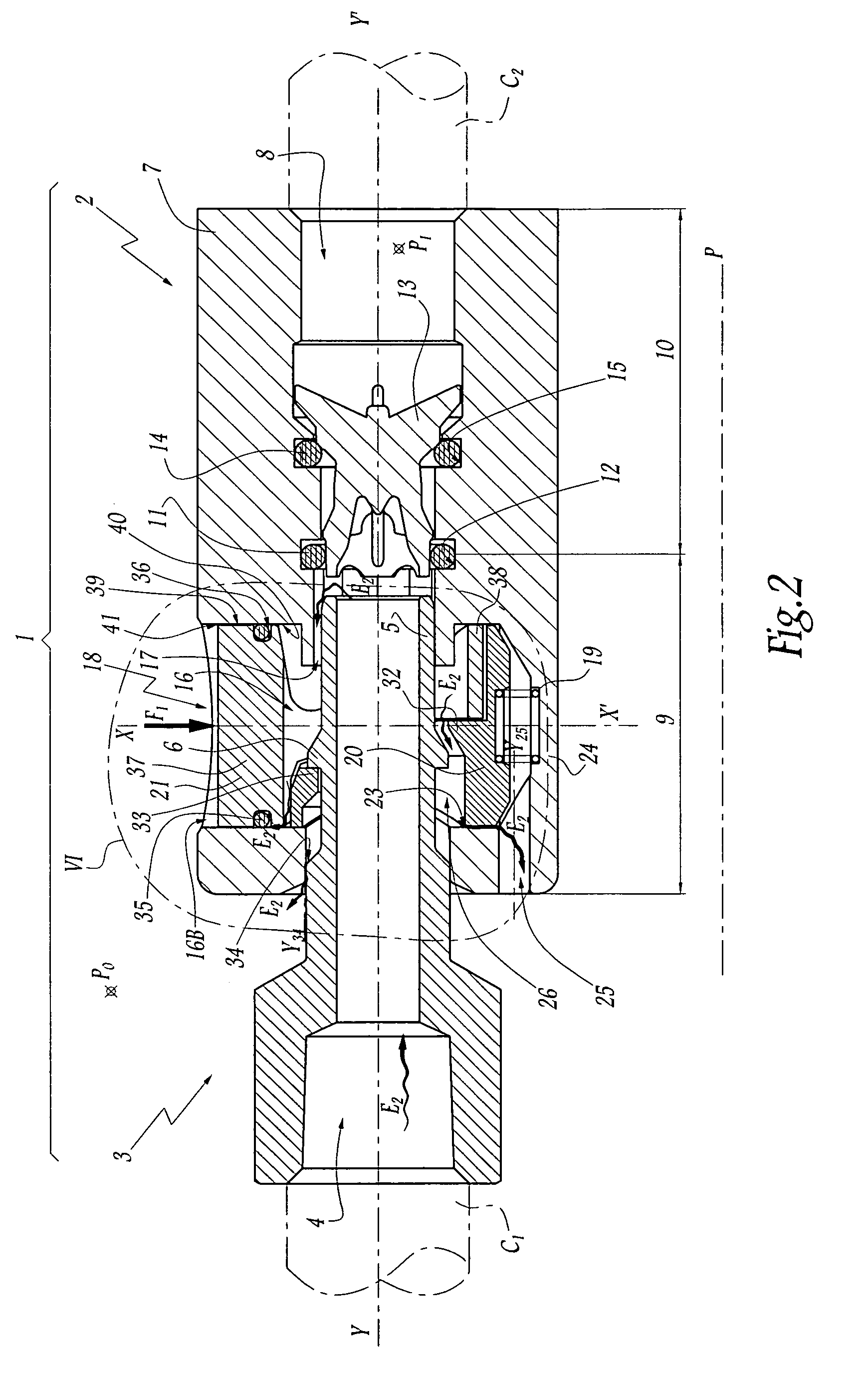
[0029]The coupling 1 comprises a female element 2 and a complementary male portion that is constituted by a male element 3 in this The elements 2 and 3 are designed to engage one in the other along the direction of an axis Y-Y′, which is a longitudinal axis common to the elements 2 and 3.

[0030]In the meaning of the invention, a proximal portion of one of the elements 2 or 3 is a portion facing or close to the pipe C1 or C2 connected to said element, whereas a distal portion is a portion facing towards or close to the other element when the elements are facing each other, ready to be engaged.

[0031]An axial passage 4 for the fluid under pressure passes through the male element 3 and opens out at both ends thereof. Coupling means for coupling one end of the passage 4 to the pipe C1, which pipe is downstream from the coupling 1 and is represented by chain-dotted lines, may be of any suitable type, and by way of example may comprise a clamping collar that is not shown for reasons of cla...

second embodiment

[0055]In FIG. 7, which is diagrammatic as are FIGS. 1 to 3, there can be seen a coupling 101 constituting the invention. Below, differences between the coupling 101 and the coupling 1 are described in greater detail. In addition, a reference used below specifying a portion of the coupling 101 that is analogous or equivalent to a reference portion of the coupling 1 is obtained by adding 100 to the reference identifying said portion of the coupling 1.

[0056]The coupling 101 in this second embodiment comprises a male element 103 and a female element 102 having its body 107 fitted with an adapter 150 having the same function as the adapter described in patent application EP 1 422 462. At its distal end, this adapter 150 has female means 151 for receiving and coupling the male plug 105 of the male element 103, while its other end defines a male plug 152. It thus constitutes a coupling element that is both male and female.

[0057]The female body 107 is also fitted with a locking mechanism 11...

fifth embodiment

[0067]Finally, the invention is described with a latch 20, 120 and a control member 21, 121 that are designed as two distinct parts. In a variant, the latch and the control member of a female coupling element of the invention could constitute a single part, and by way of example it could have a structure and a method of operation analogous to the structure and the method of operation of WO-A-2006 / 092503.


PUM


Abstract

A female element quick coupling for releasably joining two pipes conveying a fluid under pressure and which receives a male coupling wherein the female element includes a latch movable relative to a body of the female element between a first position, in which it retains the male portion in a leaktight coupling position, and a second position, in which it retains the male portion in a position for purging a downstream pipe. The female element further includes a control member mounted to slide in an open bore in the body for causing the latch to move at least towards the second position. This female element includes a gasket for closing a gap defined between an outer face of the member and an inside face of the bore especially at high purging pressures.

Description

BACKGROUND OF THE INVENTION[0001]1. Field of the Invention[0002]The present invention relates to a female coupling element and to a quick coupling for releasably joining together two pipes conveying a fluid under pressure, and including such a female element.[0003]2. Description of Related Art[0004]WO-A-2006 / 092503 describes a quick coupling comprising a female element and a male element that are connected respectively to an upstream pipe and to a downstream pipe, and that are suitable for being axially engaged one in the other. Relative engagement of the male and female elements causes a valve member mounted inside a body of the female element to open, thereby putting the upstream and downstream pipes into communication. The female coupling element includes a latch slidably mounted in the body of the female element and resiliently biased towards a position for locking the male element in its engaged configuration inside the female element. In order to separate the elements of the c...

Claims


Application Information

Patent Timeline
Patent Type & Authority Patents(United States)
IPC IPC(8): F16L37/28F16L37/36E03B1/00
CPCF16L37/0841F16L37/40F16L37/086F16L37/44Y10T137/87973
Inventor TIBERGHIEN, ALAIN-CHRISTOPHECHAMBAUD, ANTOINE
Owner STAUBLI FAVERGES SA
Why Eureka
Try Eureka