Piston for an internal combustion engine and method for its production

a technology of pistons and internal combustion engines, applied in the direction of machines/engines, manufacturing tools, mechanical apparatus, etc., to achieve the effect of good mechanical and thermal properties and reduced construction heigh

Inactive Publication Date: 2014-11-13
MAHLE INT GMBH
View PDF1 Cites 2 Cited by
  • Summary
  • Abstract
  • Description
  • Claims
  • Application Information

AI Technical Summary

Benefits of technology

[0004]The task of the present invention consists in further developing a piston of the stated type, in such a manner that the construction height is reduced, while the good mechanical and thermal properties remain the same.
[0007]The idea according to the invention consists in providing a piston having a thermally uncoupled piston skirt with a piston ring element configured as a separate component. The recess, which serves as a circumferential cooling channel in the finished piston, can be worked into the piston ring element in any desired size and construction height, and thus in advance. This eliminates the need to configure the circumferential recess, which brings about the thermal uncoupling of the piston skirt, with such a large construction height that production of the cooling channel by means of chip-cutting machining, as known for pistons according to the state of the art, is made possible in the first place. The piston according to the invention therefore makes it possible to freely select the height of the circumferential recess and thus the construction height, and to keep it as low as possible, if necessary.
[0009]A preferred further development consists in that the joining seam encloses an acute angle with the center axis of the piston. This configuration allows particularly simple use of a welding method for joining the piston components. In the case of beam welding, for example laser welding, the direction of the exiting weld beads can be controlled in such a manner that they remain outside of the cooling channel and do not impact the closure element.
[0010]It is practical if the closure element is held on the piston ring element in the region of the ring belt. This configuration allows particularly simple installation of the closure element.
[0011]Particularly preferably, the end of the joining seam on the cooling channel side lies outside of the cooling channel. In this manner, depending on the joining method used, material residues such as weld ridges that might be present are removed in simple manner. Furthermore, it is avoided that such material residues constrict or contaminate the cooling channel.

Problems solved by technology

Their relatively great construction height, which results from a minimum height of the ring-shaped recess, required due to process technology, is disadvantageous.

Method used


Image

  • Piston for an internal combustion engine and method for its production
  • Piston for an internal combustion engine and method for its production
  • Piston for an internal combustion engine and method for its production

Examples


Embodiment Construction

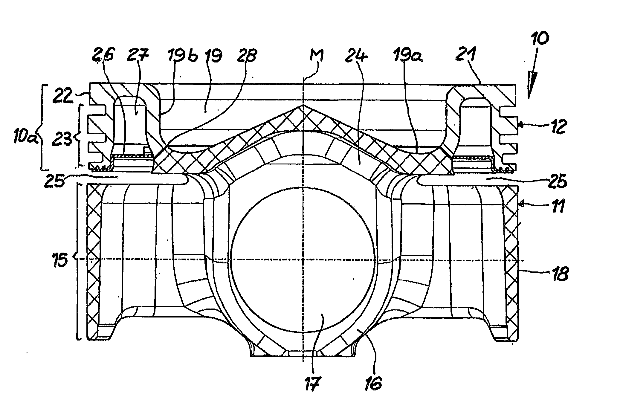
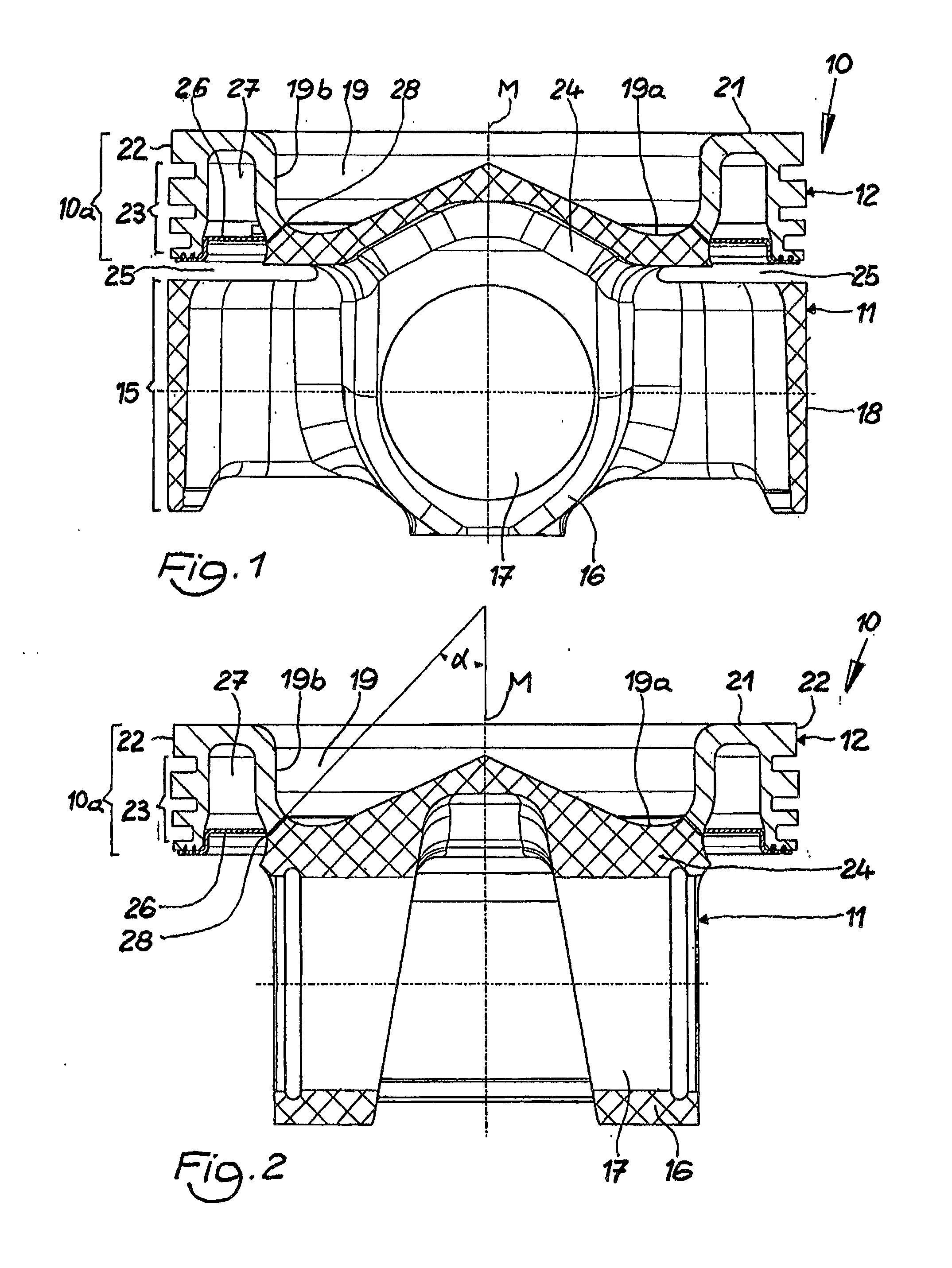
[0026]FIGS. 1 and 2 show a particularly preferred exemplary embodiment of a piston 10 according to the invention. The piston 10 has a piston base body 11 and a piston ring element 12. Both components can consist of any desired metallic material that is suitable for joining the components. The piston base body 11 and the piston ring element 12 together form the piston head 10a and the piston skirt 15 of the piston 10.

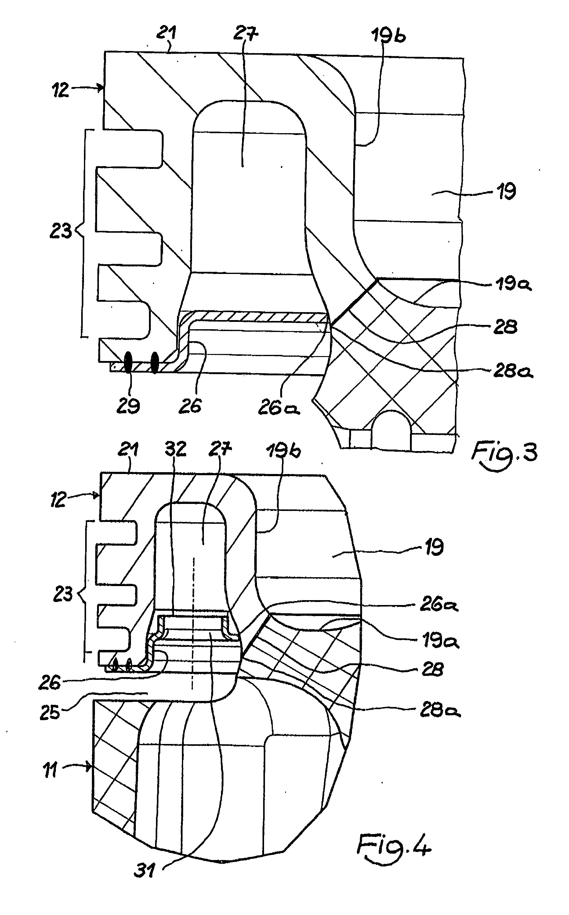
[0027]The piston base body 11 has a piston skirt 15 that is provided, in known manner, with pin bosses 16 and pin bores 17 for accommodating a piston pin, as well as with working surfaces 18. The piston ring element 12 has a piston crown 21 as well as a circumferential top land 22 and a circumferential ring belt 23 for accommodating piston rings.

[0028]The piston 10 or the piston head 10a is furthermore provided with a combustion bowl 19. In this connection, the piston base body 11 has a crown region 19a of the combustion bowl 19, while the piston ring element 12 has a wa...


PUM

PropertyMeasurementUnit
acute angleaaaaaaaaaa
strengthaaaaaaaaaa
heat resistanceaaaaaaaaaa

Abstract

A method for the production of a piston for an internal combustion engine, having a piston head, a piston skirt, and a circumferential recess configured between the piston head and the piston skirt. The piston has a piston base body and a piston ring element. The piston base body has at least a crown region of a combustion bowl as well as the piston skirt. The piston ring element has at least a piston crown, a wall region of the combustion bowl, a circumferential top land, and a circumferential ring belt with ring grooves. The piston ring element has a circumferential cooling channel between the wall region of the combustion bowl and the ring belt, closed with a closure element. The piston base body and the piston ring element are connected by a circumferential joining seam in the region of the combustion bowl.

Description

CROSS-REFERENCE TO RELATED APPLICATIONS[0001]This is a divisional of U.S. patent application Ser. No. 13 / 066,560, filed on Apr. 18, 2011, which claims priority under 35 U.S.C. 119 of German Application No. 10 2011 013 113.2 filed on Mar. 4, 2011, the disclosure of which is incorporated by reference.BACKGROUND OF THE INVENTION[0002]The present invention relates to a piston for an internal combustion engine, having a piston head, a piston skirt, and a circumferential recess configured between the piston head and the piston skirt. The present invention furthermore relates to a method for the production of such a piston.[0003]A piston of this type is known, for example, from DE 44 46 726 A1, and is also referred to as a “piston having a thermally uncoupled piston skirt.” Such pistons are characterized by great strength and by great heat resistance, because of the thermal uncoupling of piston head and piston skirt. Their relatively great construction height, which results from a minimum ...

Claims


Application Information

Patent Timeline
Patent Type & Authority Applications(United States)
IPC IPC(8): F02F3/00
CPCF02F3/00F02F2200/00B23K26/28B23P15/10F02F3/003F02F3/22Y10T29/49249Y10T29/49252B23K2101/003
Inventor BING, KARLHEINZLAPP, MICHAEL T.SCHARP, RAINERULLRICH, MICHAEL
Owner MAHLE INT GMBH
Why Eureka
Try Eureka