Wiper system for wiping a windscreen

a technology of wiper arm and windscreen, which is applied in the field of wipers, can solve the problems of reducing the service life rattling and/or overshooting, and increasing the height of the wiper arm perpendicular to the windshield, and achieves the effect of favorable wear behavior and cost-effective manufactur

Inactive Publication Date: 2007-03-29
ROBERT BOSCH GMBH
View PDF11 Cites 2 Cited by
  • Summary
  • Abstract
  • Description
  • Claims
  • Application Information

AI Technical Summary

Benefits of technology

[0006] It is the objective of the present invention to make available a four-bar wiper arm that is as flat as possible, which can be manufactured cost-effectively and has a favorable wear behavior.
[0008] One idea of the present invention consists of making a four-bar wiper device available in which the requirement for the construction height of the wiper arm is reduced since the pressure force of the wiper arm or of the wiper location connected to the wiper arm is effected on the windshield via one or both connecting rod levers. The wiper arm can be embodied to be non-articulated in particularly due to the elastic design of the connecting rod lever since the pressure force is made available via the connecting rod lever. As a result, providing articulation in the wiper arm is dispensed with in a simple way as well as a corresponding tension or compression spring, which generates the pressure force on the windshield in embodiments in accordance with the prior art. Because the articulation is dispensed with, the construction height of the wiper arm can thereby be reduced and the wiper device is less susceptible to wear.
[0009] In addition, manufacturing is greatly simplified since the connecting rod lever can be embodied as a bar spring element.

Problems solved by technology

In addition, the tension springs and their fastenings require construction space, which increases the height of the wiper arm in the perpendicular direction with respect to the windshield.
This leads to a reduction in the service life of the wiper arm and can produce rattling and / or overshooting at the wiper arm's reversing positions.

Method used


Image

  • Wiper system for wiping a windscreen
  • Wiper system for wiping a windscreen
  • Wiper system for wiping a windscreen

Examples


Embodiment Construction

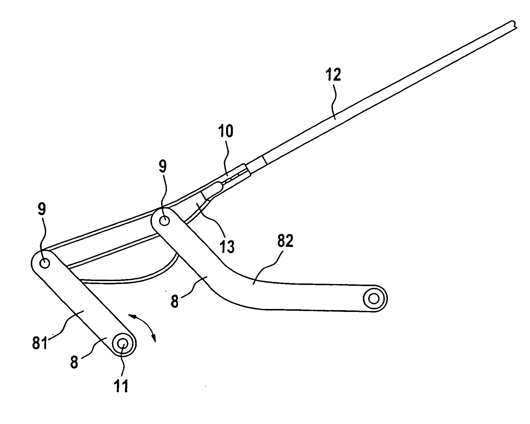
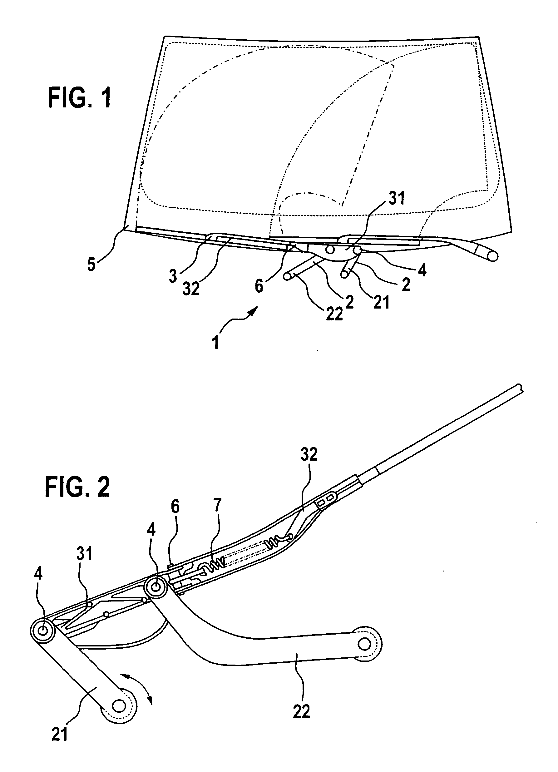
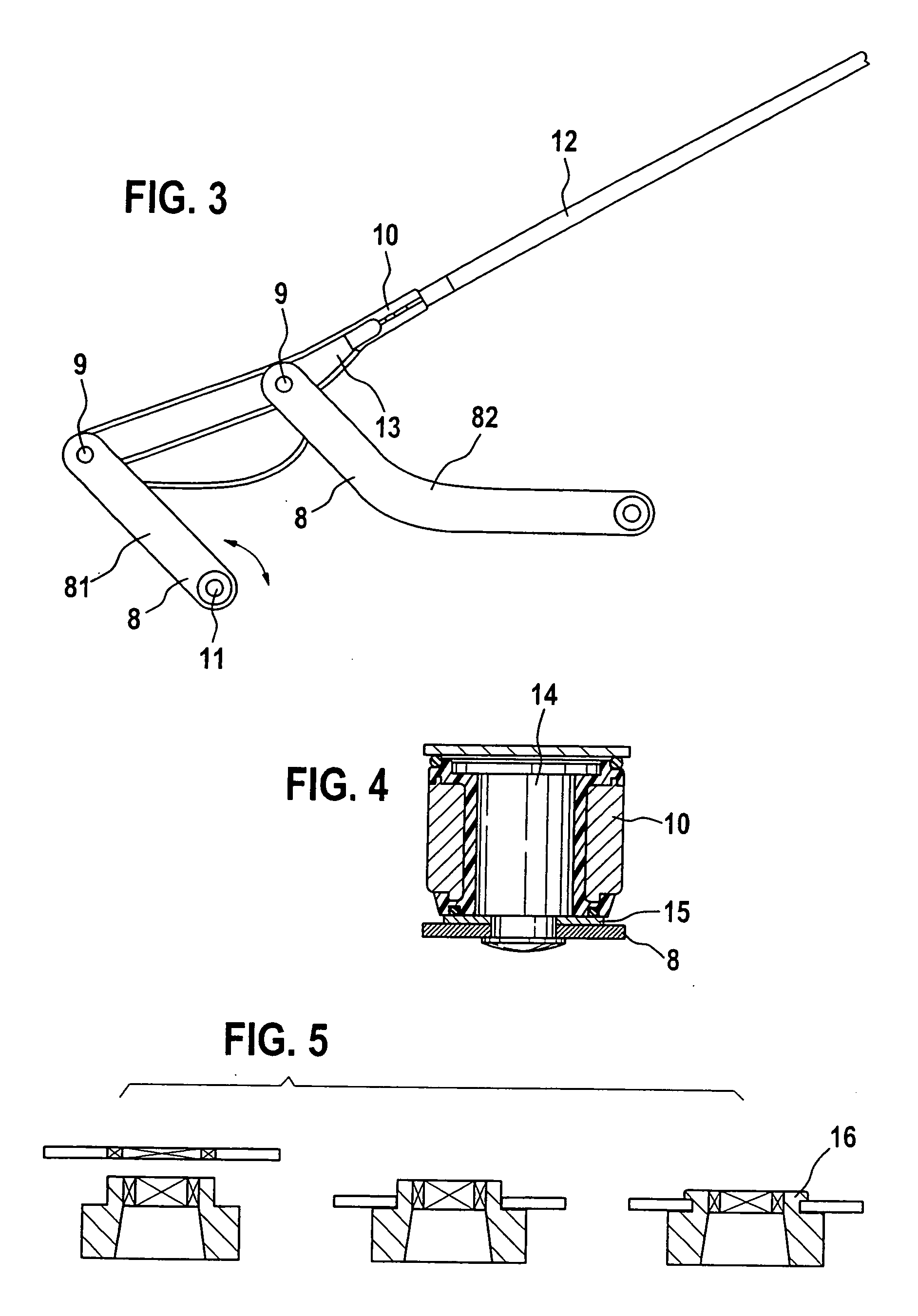
[0026]FIG. 1 depicts a wiper system like those that are used nowadays in motor vehicles. It has a wiper device 1, which is embodied as a four-bar wiper device. The four-bar wiper device features two connecting rod levers 2 with drive lever 21 and a control level 22, which are connected to a wiper arm 3 via fastening points 4. When the wiper arm 3 swivels, because of the support by the control lever 22 a lifting movement of the wiper arm 3 can occur along with the swivel movement so that the entire wiped area on the windshield 5 is increased. Driving the wiper arm 3 takes place in that the drive lever 21 is swiveled around its swivel axis 11. The control 22 effects the lifting movement of the wiper arm 3.

[0027] As can be seen in the depiction of the rear of the wiper device in FIG. 2, the wiper arm 3 has an articulation 6, which connects the coupling piece 31 and the articulated arm 32 of the wiper arm 3 with one another. A spring element is attached to the articulation 6 in such a ...


PUM


Abstract

The invention relates to a wiper device (1) to wipe a windshield (5) of a motor vehicle with a wiper arm (10) and two connecting rod levers (8), wherein the connecting rod levers (8) are connected to the wiper arm (10) in a plane at fastening points (9) so they can move rotationally, wherein at least one of the connecting rod levers (8) is executed to be elastic essentially perpendicular to the wiper plane in order to effect a pressure force from the wiper arm (10) on the windshield.

Description

BACKGROUND OF THE INVENTION [0001] The invention relates to a wiper device to wipe a windshield, in particular a wiper device with wiper arm lift control. [0002] In order to enlarge the wiped area of wiper devices, wiper arm lift controls are used, particularly in the form of four-bar wiper arms. Four-bar wiper arms essentially feature two connecting rod levers in addition to the actual wiper arm, each of which are connected to the wiper arm via an articulation. Because of an appropriate kinematic design, the wiper arm exerts a lifting and swiveling movement when the connecting rod levers are swiveled. Driving the four-bar wiper arm is accomplished via one of the two connecting rod levers, which as a drive lever is equipped with an electric drive. The second connecting rod lever, the control lever, is used to affect the lift of the wiper arm and is only fastened to a blind bearing, which does not transmit any torque. [0003] The bearing force of the wiper arm on the windshield is nor...

Claims


Application Information

Patent Timeline
Patent Type & Authority Applications(United States)
IPC IPC(8): B60S1/24B60S1/34B60S1/36B60S1/32
CPCB60S1/32B60S1/3475B60S1/3409
Inventor ZIMMER, JOACHIM
Owner ROBERT BOSCH GMBH
Why Eureka
Try Eureka