High-pass dither generator and method

Inactive Publication Date: 2008-03-06
ATI TECH INC
View PDF9 Cites 9 Cited by
  • Summary
  • Abstract
  • Description
  • Claims
  • Application Information

AI Technical Summary

Benefits of technology

[0010]Methods and circuits for generating a high-pass digital dither signal with a su

Problems solved by technology

Many common signal processing operations may result in undesirable distortions.
As a result of quantization, some information in the sample may be lost, resulting in noise referred to as quantization noise.
When smoothly shaded areas of an input image are quantized, color bands known as contours, are often observed in the quantized image due to the loss of visual information contained in the discarded

Method used


Image

  • High-pass dither generator and method
  • High-pass dither generator and method
  • High-pass dither generator and method

Examples


Embodiment Construction

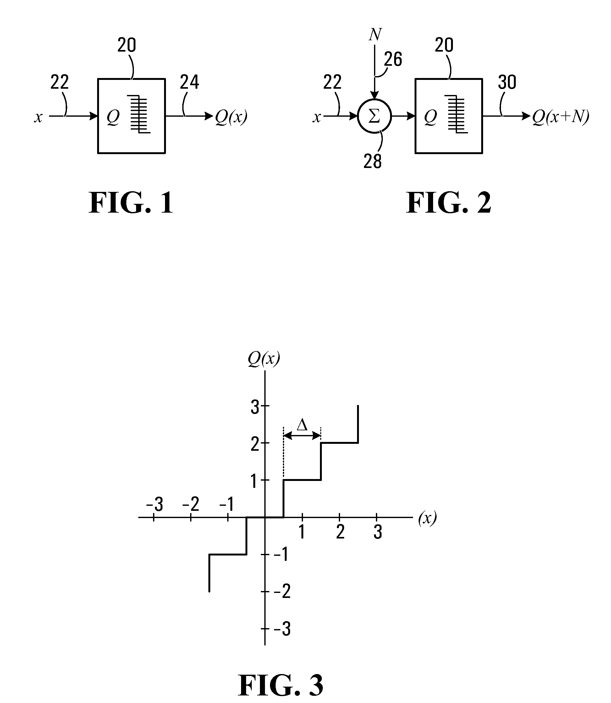
[0028]FIG. 1 illustrates a simplified block diagram of a conventional quantizer 20. Quantizer 20, denoted Q takes an input signal 22 (denoted x) and produces a quantized signal 24 (labeled Q(x)). The transfer characteristic of quantizer 20, which may be a common type of uniform quantizer, is shown in FIG. 3.

[0029]FIG. 2 illustrates a block diagram of quantizer 20 of FIG. 1 with a dither signal 26 (denoted N) added to input signal 22 prior to quantization. The output 30 of the quantizer 20 is Q(x+N). The dither signal N may be modeled as an additive random or pseudo-random process.

[0030]In many image and video processing applications, suitable dither signals are often uniformly distributed across the quantization step. This is because a uniformly distributed noise is more appealing to the eye than noise which is correlated to the input signal. For a uniformly distributed dither signal or noise, the probability density function (PDF) fN(n) of dither signal N may be defined as

fN(n)={1 / ...


PUM


Abstract

A method and circuit for generating an M-bit digital dither signal with a substantially uniform probability density function and high-pass spectrum are disclosed. The circuit includes a linear feedback shift register (LFSR) with N storage elements where N>M, and a high-pass filter. The method involves sampling at least M storage elements of the LFSR with each clock cycle to form an M-bit LFSR output and high-pass filtering and the M-bit LFSR output to provide the M-bit dither signal.

Description

FIELD OF THE INVENTION[0001]The present invention relates generally to the generation of pseudorandom data, and more particularly to generating high-pass pseudorandom data sequence useful for dithering.BACKGROUND OF THE INVENTION[0002]Many common signal processing operations may result in undesirable distortions. One such operation is the quantization of a signal. After an analog signal such as a video signal or an image is sampled, samples are typically quantized so that they can be represented as binary numbers of a finite bit size. Quantization is thus necessary to represent each sample within an allocated bit size. As a result of quantization, some information in the sample may be lost, resulting in noise referred to as quantization noise.[0003]Quantization is not limited in digital to analog signal conversion. For example, digital signals are often re-quantized. For instance, digital samples may need to be re-quantized to reduce or increase the number of bits used to represent ...

Claims


Application Information

Patent Timeline
IPC IPC(8): G06F15/00
CPCG06F7/58G06F7/584G06F2207/583H03M7/04H03M1/0641H03M1/66H03K3/84
Inventor WEI, JEFF
Owner ATI TECH INC
Why Eureka
Try Eureka