

Backlight Module with Localized Light Source Control
- Summary
- Abstract
- Description
- Claims
- Application Information
AI Technical Summary
Benefits of technology
Problems solved by technology
Method used
Image

Examples
first embodiment
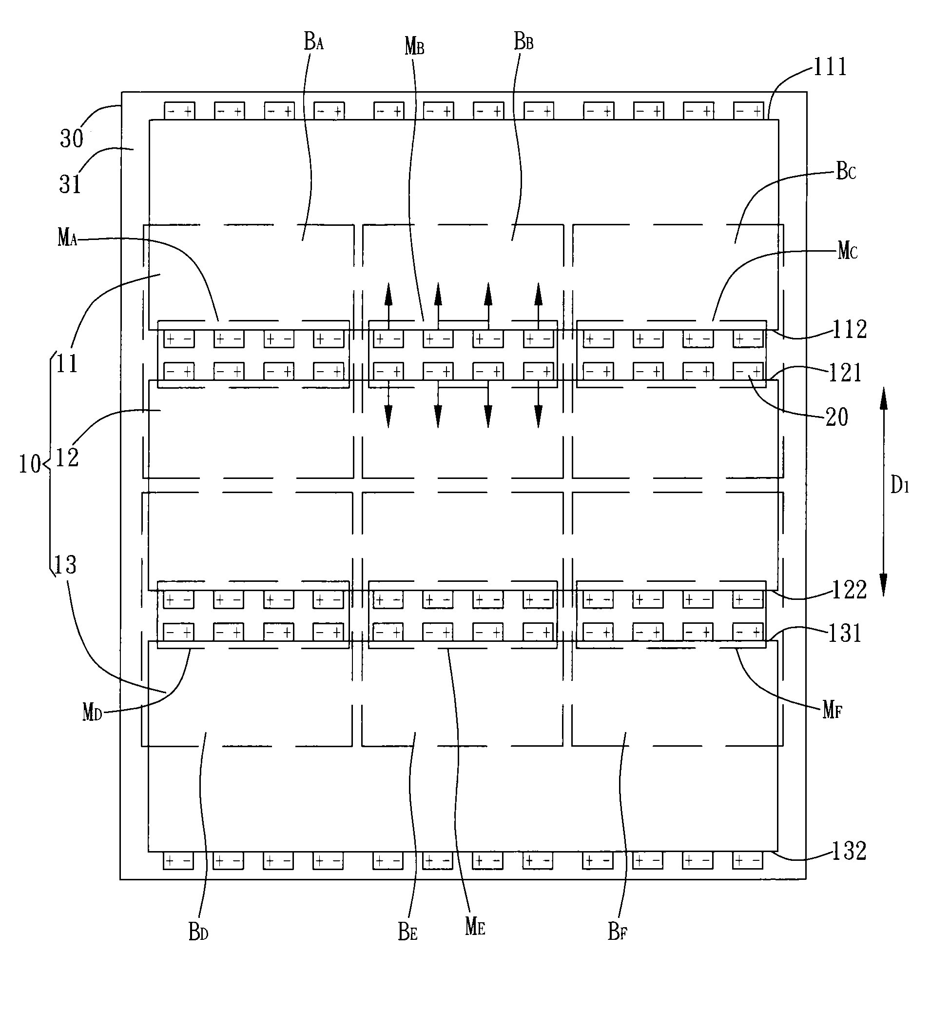
[0026]FIG. 2 is a schematic view of the backlight module of the present invention. As shown in FIG. 2, the backlight module includes a light guide plate set 10, a plurality of luminous elements 20, and a substrate 30. The light guide plate set 10 includes a first light guide plate 11, a second light guide plate 12, and a third light guide plate 13. The first light guide plate 11 has a first side 112. The second light guide plate 12 has a second side 121 and a third side 122 opposite to the second side 121. The third light guide plate 13 has a fourth side 131. The first light guide plate 11, the second light guide plate 12, and the third light guide plate 13 are disposed side by side along a first direction D1, so that the first side 112 and the second side 121 face to each other and, and the third side 122 and the fourth side 131 face to each other.
[0027]In a preferred embodiment, the luminous elements 20 are side-emitting diodes. As shown in FIG. 2, multiple luminous elements 20 ar...
second embodiment
[0033]In the embodiment as shown in FIG. 2 or FIG. 3, the substrate 30 is a rectangular circuit board which has the advantage of simple in shape and therefore easy to cut and easy to be arranged. However, in other embodiments, other type of substrate can be utilized. FIG. 5 is a schematic view of the backlight module of the present invention. As shown in FIG. 5, the backlight module includes a light guide plate set 10, a plurality of luminous elements 20, and a substrate 40. The light guide plate set 10 includes a first light guide plate 11, a second light guide plate 12, and a third light guide plate 13. The first light guide plate 11 has a first side 112; the second light guide plate 12 has a second side 121 and a third side 122 opposite to the second side 121; the third light guide plate 13 has a fourth side 131. The substrate 40 has an elongated shape. The substrate 40 between the first light guide plate 11 and the second light guide plate 12 is disposed along the first side 112...
third embodiment
[0034]As the embodiment shown in FIG. 2, FIG. 3, or FIG. 5, multiple luminous elements 20 are respectively disposed along the sides of the first light guide plate 11, the second light guide plate 12, and the third light guide plate 13, so that the luminous elements 20 disposed along the first side 112 of the first light guide plate 11 and the second side 121 of the second light guide plate 12 are opposite to each other while the luminous elements 20 disposed along the third side 122 of the second light guide plate 12 and the fourth side 131 of the third light guide plate 13 are also opposite to each other. As a result, the luminous elements 20 disposed on adjacent sides form a dual array structure. However, in other embodiments, the luminous elements 20 can be disposed in other manners. FIG. 6 is a schematic view of the backlight module of the present invention. As shown in FIG. 6, the luminous elements 20 disposed along the first side 112 of the first light guide plate 11 and the s...
PUM
 Abstract
Description
Claims
Application Information