Continuous electronic zoom for an imaging system with multiple imaging devices having different fixed fov

a technology of imaging system and electronic zoom, which is applied in the field of electronic zoom for imaging system, can solve the problems of large dynamic zoom range, large loss of information in the process, and complex design, and achieve the effect of convenient light weight electronic zoom and large lossless zooming rang

Inactive Publication Date: 2012-02-02
NEXTVISION STABILIZED SYST
View PDF5 Cites 273 Cited by
  • Summary
  • Abstract
  • Description
  • Claims
  • Application Information

AI Technical Summary

Benefits of technology

[0009]The present invention describes a continuous electronic zoom for an image acquisition system, having multiple imaging devices each with a different fixed field of view (FOV). Using two (or more) image sensors, having different fixed FOV, facilitates a light weight electronic zoom with a large lossless zooming range. For example, a first image sensor has a 60° angle of view and a second image sensor has a 60° angle of view. Therefore, Wide_FOV=Narrow_FOV*6. Hence, switching between the image sensors provide a lossless electronic zoom of 62=36. This lossless electronic zoom is also referred to herein, as the optimal zoom:Optimal_Zoom=(Wide_FOV / Narrow_FOV)2.
[0015]The method further includes the steps of providing a user of the image acquisition device with a zoom selecting control, thereby obtaining a requested zoom, selecting one of the image acquisition devices based on the requested zoom, acquiring an image frame with the selected image acquisition device, thereby obtaining an acquired image frame, and performing digitally zoom on the acquired image frame, thereby obtaining an acquired image frame with the requested zoom. The calibration of the alignment, between the first image sensor array and the second image sensor array, facilitates continuous electronic zoom with uninterrupted imaging, when switching back and forth between the first image sensor array and the second image sensor array. Preferably the electronic calibration is performed with sub-pixel accuracy.

Problems solved by technology

Typically some information is lost in the process.
Typically, a camera with a large dynamic zoom range requires heavy and expensive lenses, as well as complex design.

Method used


Image

  • Continuous electronic zoom for an imaging system with multiple imaging devices having different fixed fov
  • Continuous electronic zoom for an imaging system with multiple imaging devices having different fixed fov
  • Continuous electronic zoom for an imaging system with multiple imaging devices having different fixed fov

Examples


Embodiment Construction

[0033]Before explaining embodiments of the invention in detail, it is to be understood that the invention is not limited in its application to the details of construction and the arrangement of the components set forth in the host description or illustrated in the drawings.

[0034]Unless otherwise defined, all technical and scientific terms used herein have the same meaning as commonly understood by one of ordinary skill in the art of the invention belongs. The methods and examples provided herein are illustrative only and not intended to be limiting.

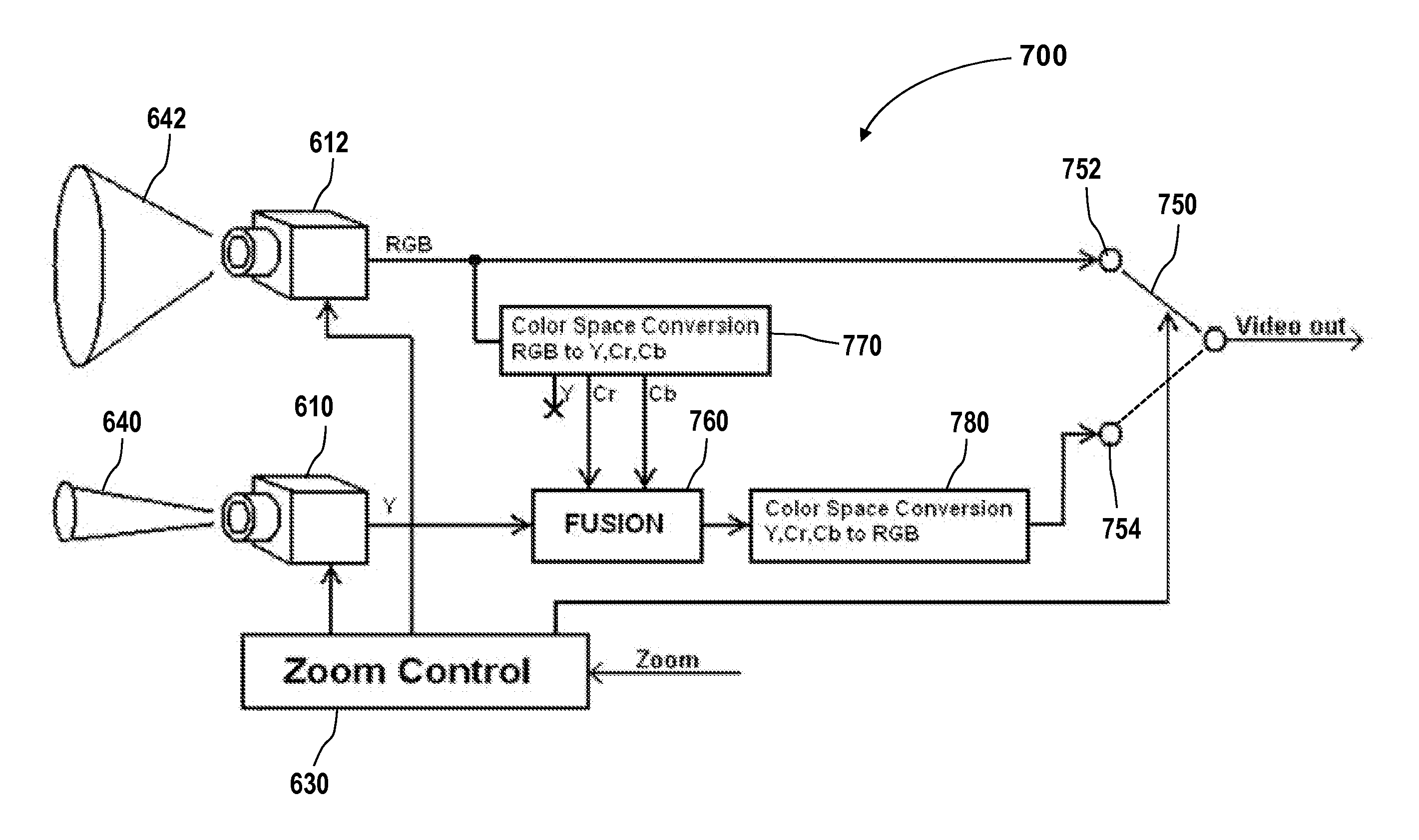
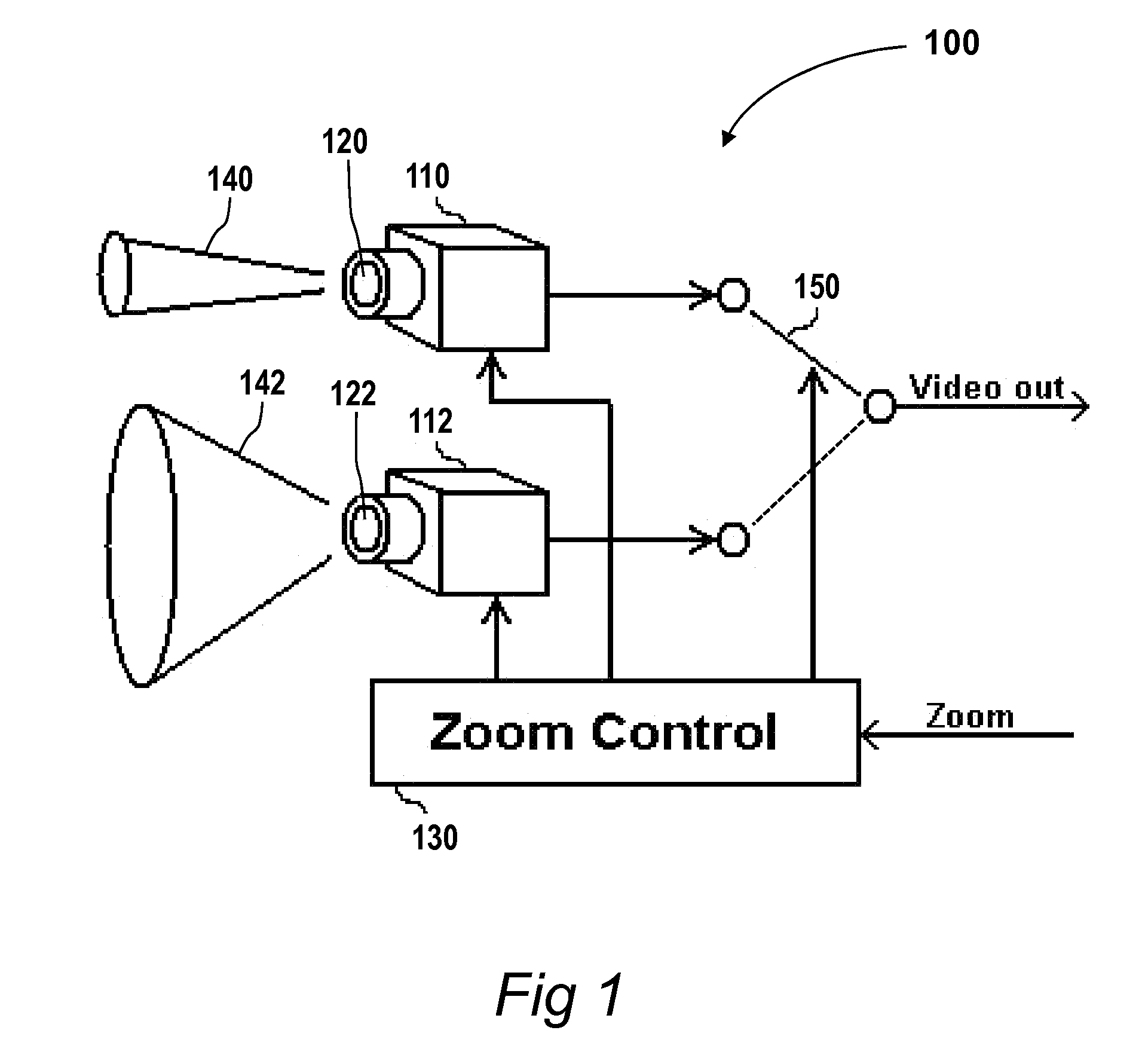
[0035]It should be noted that in general, the present invention is described, with no limitations, in terms of an image acquisition system having two image acquisition devices. But the present invention is not limited to two image acquisition devices, and in variations of the present invention, the image acquisition system can be similarly embodied with three image acquisition devices and more.

[0036]Reference is made to FIG. 1, which is a...


PUM

PropertyMeasurementUnit
angleaaaaaaaaaa
field of viewaaaaaaaaaa
angleaaaaaaaaaa

Abstract

A method for continuous electronic zoom in a computerized image acquisition system, the system having a wide image acquisition device and a tele image acquisition device having a tele image sensor array coupled with a tele lens having a narrow FOV, and a tele electronic zoom. The method includes providing a user of the image acquisition device with a zoom selecting control, thereby obtaining a requested zoom, selecting one of the image acquisition devices based on the requested zoom and acquiring an image frame, thereby obtaining an acquired image frame, and performing digitally zoom on the acquired image frame, thereby obtaining an acquired image frame with the requested zoom. The alignment between the wide image sensor array and the tele image sensor array is computed, to facilitate continuous electronic zoom with uninterrupted imaging, when switching back and forth between the wide image sensor array and the tele image sensor array.

Description

RELATED APPLICATION[0001]The present application claims the benefit of U.S. provisional application 61 / 167,226 filed on Apr. 7, 2009, the disclosure of which is incorporated herein by reference.FIELD OF THE INVENTION[0002]The present invention relates to an electronic zoom for imaging systems, and more particularly, the present invention relates to a continuous electronic zoom for an image acquisition system, the system including multiple imaging devices having different fixed FOV.BACKGROUND OF THE INVENTION AND PRIOR ART[0003]Digital zoom is a method of narrowing the apparent angle of view of a digital still or video image. Electronic zoom is accomplished by cropping an image down to a centered area of the image with the same aspect ratio as the original, and usually also interpolating the result back up to the pixel dimensions of the original. It is accomplished electronically, without any adjustment of the camera's optics, and no optical resolution is gained in the process. Typic...

Claims


Application Information

Patent Timeline
Patent Type & Authority Applications(United States)
IPC IPC(8): H04N5/262
CPCH04N5/232H04N5/23258Y10T29/49826H04N5/2628H04N5/23248H04N5/23264H04N23/682H04N23/6812H04N23/683H04N23/687H04N23/695H04N23/68
Inventor GOLAN, CHENKIPNIS, BORIS
Owner NEXTVISION STABILIZED SYST
Why Eureka
Try Eureka