Zoom lens system, imaging device and camera
a zoom lens and imaging device technology, applied in the field of zoom lens systems, can solve the problems of low zoom ratio and not meet the requirements of digital cameras, and achieve the effects of high resolution, small size and high zoom ratio of 12
- Summary
- Abstract
- Description
- Claims
- Application Information
AI Technical Summary
Benefits of technology
Problems solved by technology
Method used
Image

Examples
embodiments 1 to 5
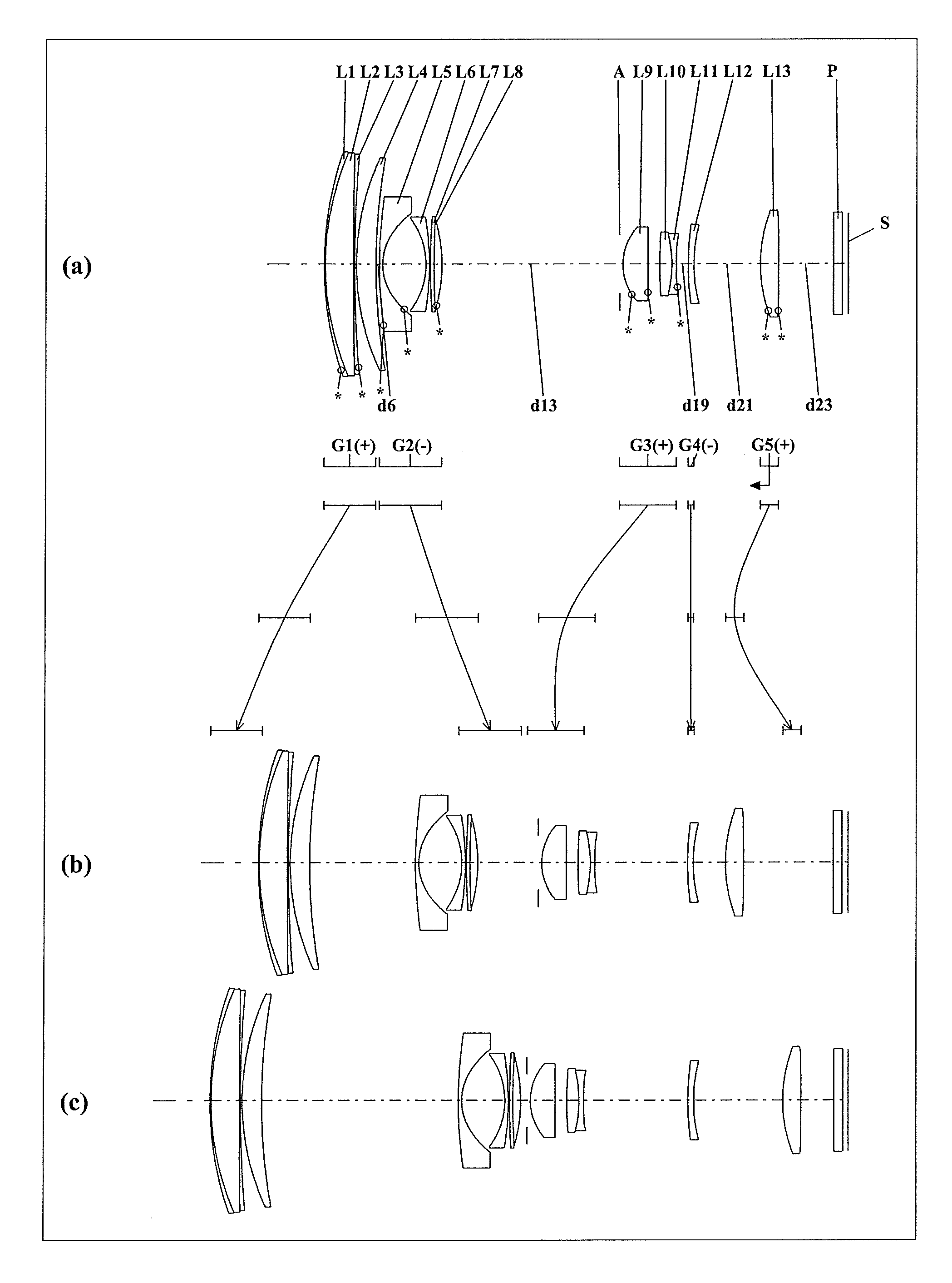
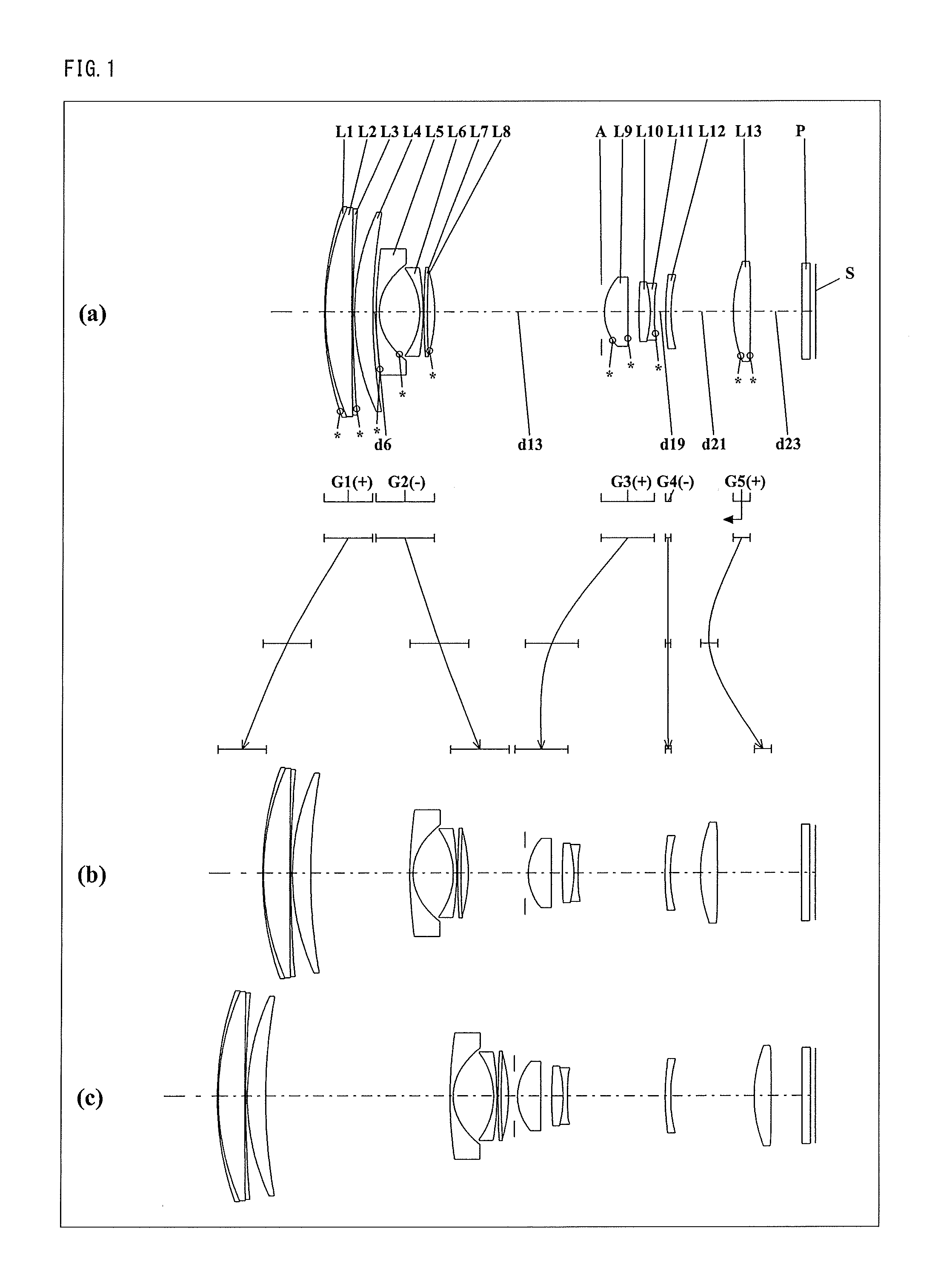
[0110]FIGS. 1, 4, 7, 10, and 13 are lens arrangement diagrams of zoom lens systems according to Embodiments 1 to 5, respectively.
[0111]Each of FIGS. 1, 4, 7, 10, and 13 shows a zoom lens system in an infinity in-focus condition. In each Fig., part (a) shows a lens configuration at a wide-angle limit (in the minimum focal length condition: focal length fW), part (b) shows a lens configuration at a middle position (in an intermediate focal length condition: focal length fM=√(fW*fT)), and part (c) shows a lens configuration at a telephoto limit (in the maximum focal length condition: focal length fT). Further, in each Fig., an arrow of straight or curved line provided between part (a) and part (b) indicates the movement of each lens unit from a wide-angle limit through a middle position to a telephoto limit. Moreover, in each Fig., an arrow imparted to a lens unit indicates focusing from an infinity in-focus condition to a close-object in-focus condition. That is, the arrow indicates t...
embodiment 6
[0216]FIG. 16 is a schematic construction diagram of a digital still camera according to Embodiment 6. In FIG. 16, the digital still camera comprises: an imaging device having a zoom lens system 1 and an image sensor 2 composed of a CCD; a liquid crystal display monitor 3; and a body 4. The employed zoom lens system 1 is a zoom lens system according to Embodiment 1. In FIG. 16, the zoom lens system 1, in order from the object side to the image side, comprises a first lens unit G1, a second lens unit G2, an aperture diaphragm A, a third lens unit G3, a fourth lens unit G4, and a fifth lens unit G5. In the body 4, the zoom lens system 1 is arranged on the front side, while the image sensor 2 is arranged on the rear side of the zoom lens system 1. On the rear side of the body 4, the liquid crystal display monitor 3 is arranged, while an optical image of a photographic object generated by the zoom lens system 1 is formed on an image surface S.
[0217]The lens barrel comprises a main barre...
numerical example 1
[0230]The zoom lens system of Numerical Example 1 corresponds to Embodiment 1 shown in FIG. 1. Table 1 shows the surface data of the zoom lens system of Numerical Example 1. Table 2 shows the aspherical data. Table 3 shows the various data.
TABLE 1(Surface data)Surface numberrdndvdθgFObject surface∞ 1*29.706500.100001.8780613.10.751 224.563802.462401.6229958.1 3568.864100.100001.5926612.20.281 4*118.842400.15000 522.065001.694901.8042046.5 651.65800Variable 7*36.607200.300001.8047041.0 8*4.733703.79350 9−6.582600.300002.0010029.110−25.003800.100001165.936600.300001.9459518.01265.936500.700001.7599812.90.63513*−13.55230Variable14(Diaphragm)∞0.3000015*4.775502.189301.5833259.116*3671.380701.038401736.759701.072301.4874970.418−11.008900.400001.8211524.119*51.28740Variable2025.266200.500002.0010029.12113.17010Variable22*12.715401.595401.5833259.123*−500.00000Variable24∞0.800001.5168064.225∞(BF)Image surface∞
TABLE 2(Aspherical data)Surface No. 1K = 0.00000E+00, A4 = −8.81318E−06, A6 = 1.3...
PUM
 Abstract
Description
Claims
Application Information
 - R&D
- Intellectual Property
- Life Sciences
- Materials
- Tech Scout
- Unparalleled Data Quality
- Higher Quality Content
- 60% Fewer Hallucinations
Browse by: Latest US Patents, China's latest patents, Technical Efficacy Thesaurus, Application Domain, Technology Topic, Popular Technical Reports.
© 2025 PatSnap. All rights reserved.Legal|Privacy policy|Modern Slavery Act Transparency Statement|Sitemap|About US| Contact US: help@patsnap.com