Logical data model abstraction in a physically distributed environment

a physical distributed environment and data model technology, applied in the field of client/server based applications and client based data models, can solve the problems of considerable computing power of such devices, and absolute computing power pale in comparison to the computing power of a server or server farm

Active Publication Date: 2012-02-02
SAP AG
View PDF8 Cites 13 Cited by
  • Summary
  • Abstract
  • Description
  • Claims
  • Application Information

AI Technical Summary

Benefits of technology

[0006]Features of the invention include one or more of the following. The controller can include an event handler to respond to events generated within the graphical user interface. The event handler can bind data used by the component object to a data source. The data source can be remotely located on a server computer or can be located in a second component object located on the same computer. The component object's data model can include a flag that indicates when the data binding between the component and the data source is valid. The component object's event handler can respond to an event within the graphical user interface by calling a local script to calculate the value of a data element within the component object. The component object's data model can include a flag that indicates when the value of a component object data element has changed. The component object can be instantiated on a client computer, and can be configured to communicate with a corresponding component object that is instantiated on a server computer. The client instantiated component object and the server instantiated component object can exchange data. The data exchanged between the client instantiated component object and the server instantiated component object can be limited to data that needs to be exchanged to maintain the current state of a user interface in the client computer.
[0007]Other features of the invention include one or more of the following. A bound property framework allows the client runtime to receive event notifications of changes that are made to data fields that are not in the current scope, focus, or lead selection of the user interface. As a general rule, component objects are only populated in the client runtime if they are within the current scope or focus of the user interface. As a result, changes made to the values of data fields that are out of the current scope, focus or lead selection of the user interface are generally not visible to the client runtime. The bound property framework allows a proxy object to be created within the client runtime, having a logical path to a data field within the data model, which is alerted to changes in the data field regardless of whether the data field is within the current focus, scope or lead selection of the user interface or client runtime.

Problems solved by technology

While the computing power of such devices is considerable, it nonetheless pales in comparison to the computing power of a server or server farm.
While such computers provide rich graphical user interfaces and posses considerable computing power in their own right, absolute computing power pales in comparison to the computing power of a server or server farm.
As a result, many computationally intensive applications are most effectively run on servers or server farms.
Depending on the number and size of the customers, such records can be voluminous, and maintaining and analyzing them can be a computationally intensive task that is best left to an enterprise server or server farm.
This not only increases the burden placed on the client side devices, which need different clients or client components to interface with different server applications, but also increases the burden on the server, which needs to maintain different interfaces for the different clients or client components.

Method used


Image

  • Logical data model abstraction in a physically distributed environment
  • Logical data model abstraction in a physically distributed environment
  • Logical data model abstraction in a physically distributed environment

Examples


Embodiment Construction

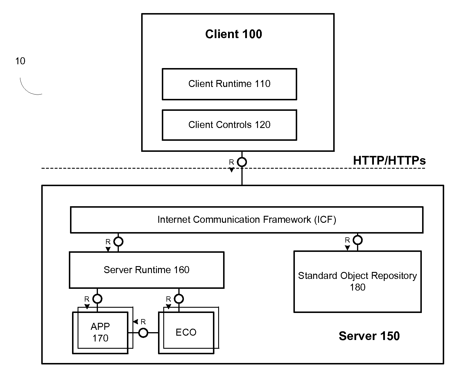
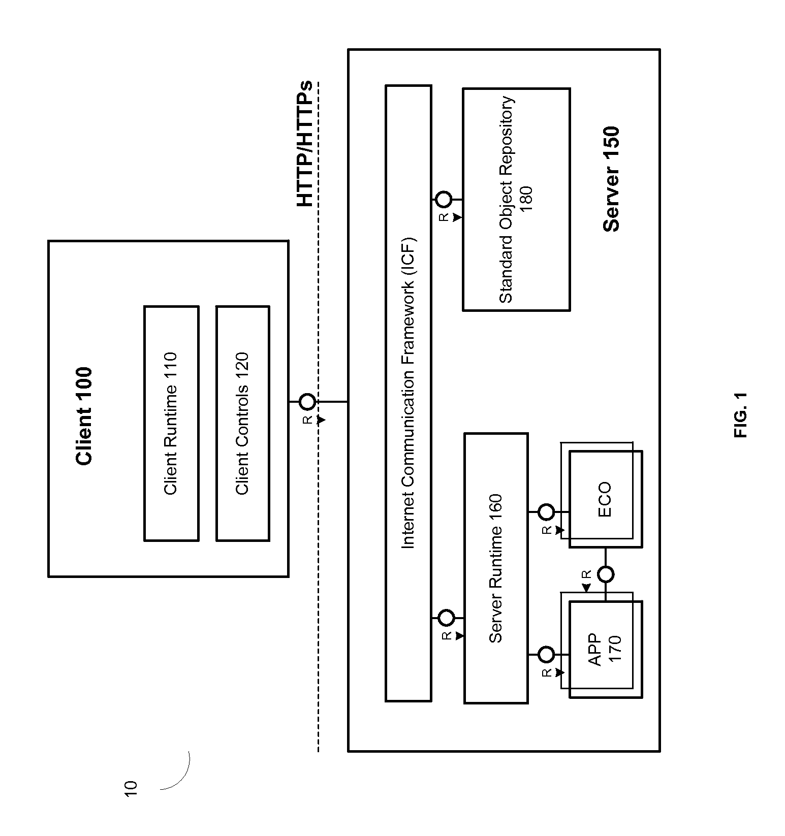
[0013]FIG. 1 is a block diagram of a system 10 for executing an application using a client-server architecture. As shown in FIG. 1, system 10 includes a client computer 100 and a server computer 150. The client computer 100 runs a client runtime 110 that includes one or more controls 120. The server computer 150 runs a server runtime 160 and a backend application 170. The client runtime 110 generates and renders a graphical user interface (GUI) that allows a user of client computer 100 to graphically interact with and control the backend application 170 on server 150. The server runtime 160 communicates with both the client runtime 110 on client computer 100 and the backend application 170 on server 150. The server runtime 160 reads, writes, interprets, and translates data from backend application170 into one or more declared UI component objects (see, FIG. 2) using a data model that is common to both the client runtime 110 and the server runtime 160. Preferably, the client runtime ...


PUM


Abstract

A component object binds business driven services to a graphical user interface (GUI). The object includes a data model, view model and controller. The view model graphically presents, and the controller manipulates data used by the object. The controller includes an event handler that respond to events generated within the GUI and binds data used by the object to a data source which can be another component object or a remotely located source. The event handler can call a local script to calculate the value of a data element within the object. The component object can be instantiated on a client, and can be configured to communicate with a corresponding component object on a server. The client and server component objects can exchange only that data that needs to be exchanged to maintain the current state of a user interface in the client computer.

Description

TECHNICAL FIELD[0001]This description relates to client / server based applications, and client based data models for accessing and interfacing with data derived from server based applications.BACKGROUND[0002]Today, business is often conducted via portable and hand-held computers. Devices such as smart phones, personal digital assistants, tablet based computers and netbooks, to name just a few, have a small physical footprint yet a rich graphical user interface. As such, they are well suited for data presentation and remote business use. While the computing power of such devices is considerable, it nonetheless pales in comparison to the computing power of a server or server farm. The same can be said of desktop and laptop computers. While such computers provide rich graphical user interfaces and posses considerable computing power in their own right, absolute computing power pales in comparison to the computing power of a server or server farm. As a result, many computationally intens...

Claims


Application Information

Patent Timeline
Patent Type & Authority Applications(United States)
IPC IPC(8): G06F3/048G06F9/44G06F15/16
CPCG06F9/4443G06F9/451
Inventor DEMANT, HILMARDROLL, SEBASTIANFITZER, JOACHIMGRAMMATIKAKIS, IOANNISHEILER, JANSATTLER, JUERGENSCHERTEL, FRANKVIOL, MARKUSWEBER, THORSTEN
Owner SAP AG
Why Eureka
Try Eureka